LED display correction system

A display calibration and acquisition system technology, applied to static indicators, instruments, etc., can solve the problems of high difficulty in on-site calibration, large calibration errors, and low calibration efficiency, and achieve the effect of simple and convenient maintenance or update work and improved calibration accuracy

Pending Publication Date: 2017-06-27
上海得倍电子技术有限公司
View PDF5 Cites 9 Cited by
  • Summary
  • Abstract
  • Description
  • Claims
  • Application Information

AI Technical Summary

Problems solved by technology

Therefore, the current point-by-point calibration method of LED display screens has disadvantages such as inability to correct due to environmental reasons, low calibration efficiency, and large calibration errors. At the same time, this calibration method requires a lot of manpower, material resources and time, and has low economic benefits.
[0005] For the current problems of large-screen calibration and on-site calibration that are difficult in engineering, no effective solution has been proposed so far

Method used


Image

  • LED display correction system
  • LED display correction system
  • LED display correction system

Examples


Embodiment Construction

[0028] In the following description, the present invention is described with reference to various examples. One skilled in the art will recognize, however, that the various embodiments may be practiced without one or more of the specific details, or with other alternative and / or additional methods, materials, or components. In other instances, well-known structures, materials, or operations are not shown or described in detail so as not to obscure aspects of the various embodiments of the invention. Similarly, for purposes of explanation, specific quantities, materials and configurations are set forth in order to provide a thorough understanding of embodiments of the invention. However, the invention may be practiced without these specific details. Furthermore, it should be understood that the various embodiments shown in the drawings are illustrative representations and are not necessarily drawn to scale.

[0029] In this specification, reference to "one embodiment" or "the...


PUM


Abstract

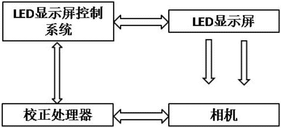
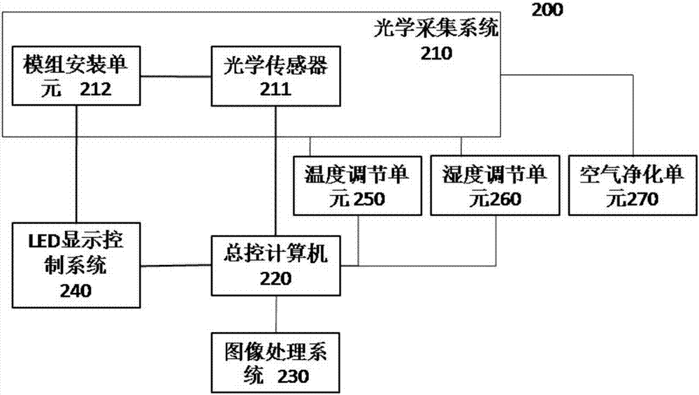
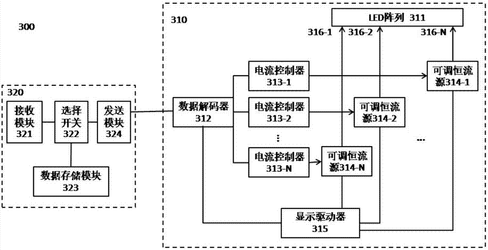
The invention discloses an LED display correction system, including an optical collection system, an LED display control system and a main control computer. The optical collection system comprises an enclosed case, a module installation unit and an optical collection unit. The module installation unit is arranged at one end of the enclosed case and is used for holding a to-be-corrected LED display unit. The optical collection unit is arranged at the other end of the enclosed case and is used for collecting display information of the LED display unit. The LED display control system is connected to the to-be-corrected LED display unit to control the to-be-corrected LED display unit to emit light. The main control computer is connected to an optical sensor, and is used for receiving the display information collected by the optical collection system and sending the display information to an image processing system for image processing, so as to obtain correction data.

Description

technical field [0001] The invention relates to the field of LED correction, in particular to an LED display correction system. Background technique [0002] Usually, a large LED display is spliced ​​by multiple LED display modules. Due to the manufacturing process and other reasons, the performance of each LED chip has certain differences. For example, there may be a 20% difference in the brightness of the LED chip, that is, the three channels of red, green, and blue have a 20% difference in brightness; at the same time, due to the pressure of manufacturing costs, LED chips with a wavelength difference within 5nm are generally regarded as qualified. , so there is also a certain color difference. When the display modules made of these different LED chips are integrated into an LED display, if these differences are not sufficiently compensated, there will be differences in the brightness and color of the LED display visible to the naked eye. In addition, during the use of ...

Claims


Application Information

Patent Timeline
Patent Type & Authority Applications(China)
IPC IPC(8): G09G3/32
CPCG09G3/32G09G2320/0693G09G2320/06G09G2300/026
Inventor 解维祺乔红瑗杨晓鹏丁佳卿
Owner 上海得倍电子技术有限公司
Why Eureka
Try Eureka