Unmanned aerial vehicle for deicing and accumulated snow removing of aerial cable

A technology of high-altitude cables and drones, which is applied in the field of drones and can solve problems such as long cycle time and difficult repair work

Inactive Publication Date: 2017-06-27
四川智航慧飞无人机科技有限公司
View PDF5 Cites 11 Cited by
  • Summary
  • Abstract
  • Description
  • Claims
  • Application Information

AI Technical Summary

Problems solved by technology

[0004] The consequences of power interruptions caused by ice and snow, or even disconnection of the power grid, are usually extremely serious, and the repair work is difficult and takes a long time

Method used


Image

  • Unmanned aerial vehicle for deicing and accumulated snow removing of aerial cable
  • Unmanned aerial vehicle for deicing and accumulated snow removing of aerial cable

Examples


Embodiment 1

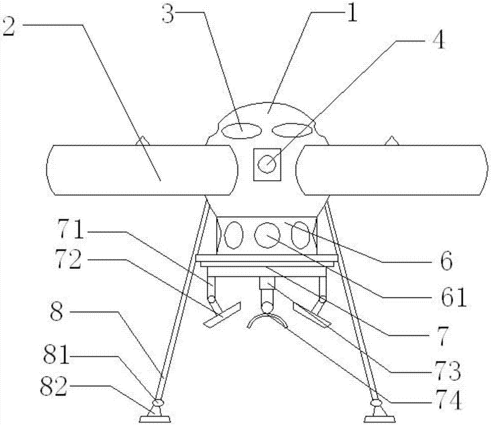
[0020] like figure 1 , 2 As shown, in the present invention, the unmanned aerial vehicle for deicing and snow removal of high-altitude cables includes a rotor protective cover 2 oppositely installed on the side end surface of the body 1, and a rotor 5 is installed on the outer end surface of the upper part of the body 1 in the rotor protective cover 2. Airflow holes 3 are arranged on the top, and the airflow holes 3 are oppositely arranged. A camera 4 is installed on the front end surface of the body 1. The bottom of the body 1 is connected to the connecting frame 6. The connection method is welding. Hole 61, the bottom of the connecting frame 6 is connected with the operation platform 7, the outside of the bottom surface of the operation platform 7 is provided with an adjustable rocker 71, one end of the adjustable rocker 71 is connected with the operation platform, and the other end is connected with the fan 72, and the bottom surface of the operation platform 7 End face mi...

Embodiment 2

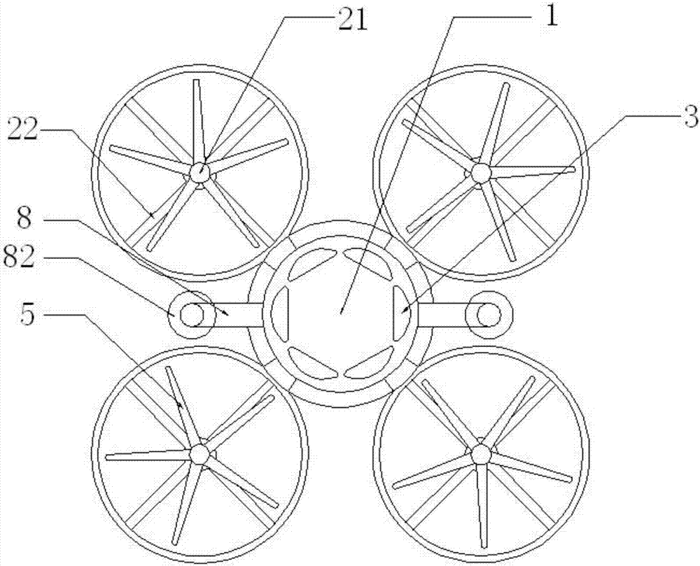
[0022] like figure 1 As shown, the only difference between this embodiment and the first embodiment is that a spherical hinge is installed in the middle of the adjustable rocker 71, so that the shape of the fan 72 can be adjusted according to the situation. Described rotor protective cover 2 is circular in shape, and engine 21 is installed on the circle center of rotor protective cover 2, and rotor 5 is connected with engine 21, and protective bracket 22 is installed on the bottom of rotor protective cover 2 horizontal end faces, and one end of protective bracket 22 is connected on the rotor. On the inner wall of the protective cover 2, the other end is installed on the outer end surface of the lower part of the engine 21. The air flow enters through the flow holes 61 , passes through the body 1 , and flows out through the air flow holes 3 . The protective bracket 22 is used to place foreign objects into the inside of the rotor protective cover 2, thereby damaging the engine ...


PUM


Abstract

The present invention discloses an unmanned aerial vehicle for deicing and accumulated snow removing of an aerial cable. A rotor wing protective cover is oppositely installed at the end surface of one side of the vehicle body, the rotor wing protective cover is internally provided with a rotor wing, air holes are arranged at the end surface of the outer side of the upper portion of the vehicle body, the air holes are oppositely arranged, a camera is installed at the end surface of the front portion of the vehicle body, and the lower portion of the vehicle body is connected with a connection rack, the connection mode is welding, circulation holes are arranged at the end surface of the side of the connection rack, the lower portion of the connection rack is connected with a work platform, a controllable rocking bar is arranged at the outer side of the end surface of the bottom portion of the work platform, one end of the controllable rocking bar is connected with the work platform, the other end of the controllable rocking bar is connected with a fan, an expansion link is arranged at the middle portion of the end surface of the bottom of the work platform, the axis of the expansion link is perpendicular to the work platform, one end of the expansion link is connected with the work platform, and the other end of the expansion link is connected with a snow removing arm, and the snow removing arm is configured to remove ice and snow on a line.

Description

technical field [0001] The invention relates to an unmanned aerial vehicle, in particular to an unmanned aerial vehicle for deicing and snowing high-altitude cables. Background technique [0002] Ice and snow covering transmission lines in winter is one of the biggest natural disasters in the power system. When cold raindrops fall on objects with a temperature below freezing point (0°C), it is easy to form rime. If it is condensed on the wire, it will form wire icing. If all wires within a range are encased in ice, this is icing. When snow falls, snow is easy to accumulate above the line, which can easily cause lines, base stations, etc. to be crushed and deformed, thereby affecting work. [0003] For high-voltage wires for long-distance power transmission, they rely on iron towers for support. Ice and snow cover the towers to increase their load. Severe ice and snow cover may even make the towers unable to support the wires and collapse. However, if the insulator strings...

Claims


Application Information

Patent Timeline
Patent Type & Authority Applications(China)
IPC IPC(8): H02G7/16
CPCH02G7/16
Inventor 罗洪源
Owner 四川智航慧飞无人机科技有限公司
Why Eureka
Try Eureka