Connection joint of climbing tower crane supporting frame and wall body and implementation method

A technology for connecting nodes and implementing methods, applied in the field of climbing tower cranes, can solve the problems of stress concentration, easy deformation of the ear plate to the outside, large ear plate, etc., and achieves the effect of saving construction period, facilitating safety monitoring, and improving efficiency.

Active Publication Date: 2017-06-30
CHINA CONSTR THIRD ENG BUREAU GRP CO LTD
View PDF9 Cites 5 Cited by
  • Summary
  • Abstract
  • Description
  • Claims
  • Application Information

AI Technical Summary

Problems solved by technology

In this way, on the one hand, when the two ears on the embedded part bear the lateral horizontal force, only one side of the ear plate is always subjected to force due to extrusion force transmission, resulting in stress concentration, and the ear plate is designed to be thicker and larger; On the one hand, when the side lug plate of the embedded part is welded on site, it can only be welded with a single-sided break, and the lug plate is easily deformed to the outside, and an additional fixing plate must be added to fix it during the on-site construction; moreover, the tower crane is a major construction equipment. Safety is of great concern, and there is no better way to know the force between it and the wall on site

Method used


Image

  • Connection joint of climbing tower crane supporting frame and wall body and implementation method
  • Connection joint of climbing tower crane supporting frame and wall body and implementation method
  • Connection joint of climbing tower crane supporting frame and wall body and implementation method

Examples


Embodiment approach

[0031] A method for implementing the connection node between the support frame and the wall of the climbing tower crane, comprising the following steps:

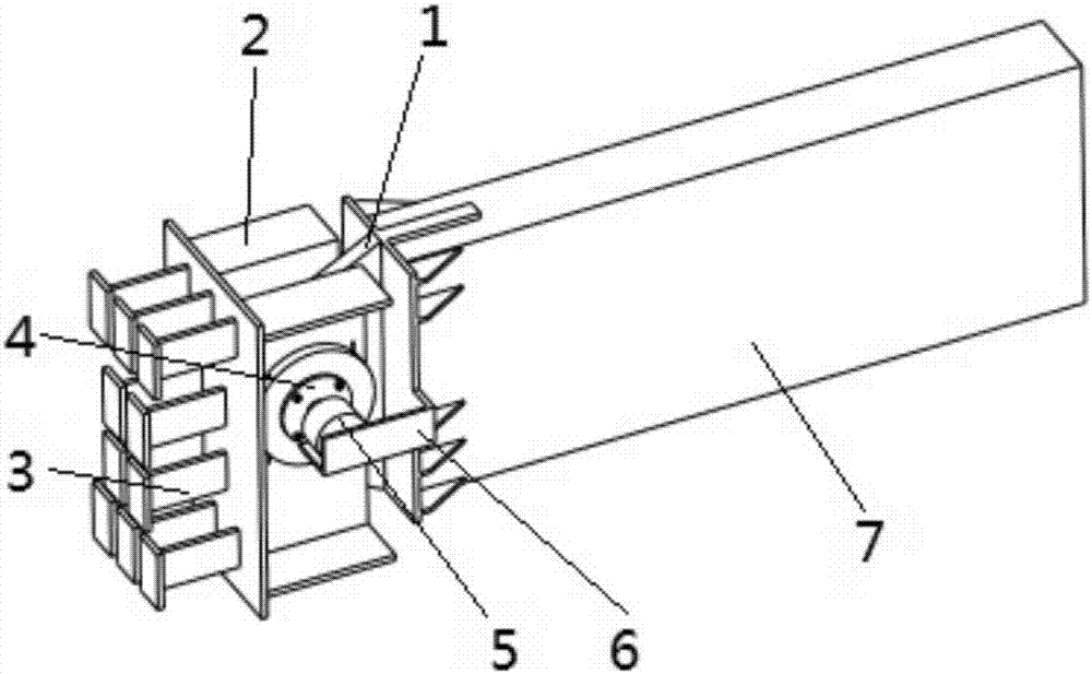
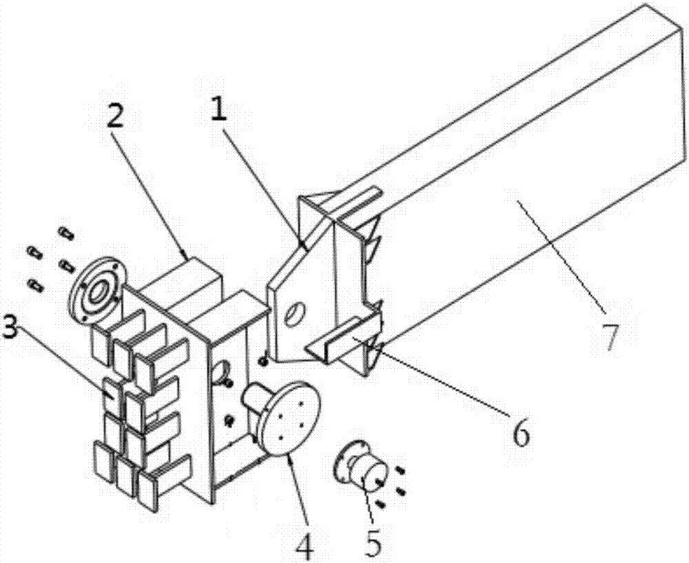
[0032] S1. Weld the second connecting lug plate 2 on the side of the embedded part 3; the two sides of the second connecting lug plate 2 are connected with a constraining plate having a certain angle with the second connecting lug plate 2, and the constraining plate is used to ensure the second connection during welding The lug plate 2 is perpendicular to the embedded part 3, so that the second connecting lug plate 2 can be prevented from being deformed to the outside without a fixing plate during welding.

[0033] S2. Insert the first connecting lug 1 on the side of the main beam 7 of the support frame between the second connecting lugs 2, and insert the pin 4.

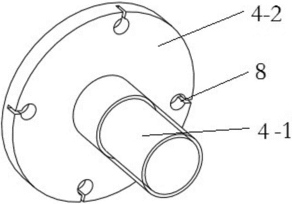
[0034] S3. Put the pre-tightening force applying device 5 on the mounting bracket 6 to apply a pre-tightening force to the pin shaft 4 . A pressure sensor 8 is pr...


PUM


Abstract

The invention provides a connection joint of a climbing tower crane supporting frame and a wall body. The connection joint comprises a first connection lug plate arranged on the supporting frame main beam side, second connection lug plates arranged on the embedded part side, a pin shaft used for connecting the first connection lug plate with the second connection lug plates, a pre-tightening force applying device used for providing pre-tightening force for the pin shaft, and an installation bracket used for supporting the pre-tightening force applying device. The number of the first connection lug plate is one. The number of the second connection lug plates is two. The first connection lug plate is arranged between the two second connection lug plates. The first connection lug plate and the second connection lug plates are provided with through holes allowing the pin shaft to pass. The pre-tightening force applying device is arranged on the outer side of the pin shaft. The installation bracket is connected with the embedded part side or the supporting frame main beam side. According to the connection joint of the climbing tower crane supporting frame and the wall body, by arranging the pin shaft and the pre-tightening force applying device, horizontal force is effectively and uniformly transmitted to the two second connection lug plates arranged on the embedded part side through the pin shaft applied with the pre-tightening force, the situation that each second connection lug plate on the unilateral side is independently stressed is avoided, the thickness and the size of the lug plates can be decreased, and the cost is reduced.

Description

technical field [0001] The invention belongs to the field of climbing tower cranes, and in particular relates to a connection node between a support frame and a wall of a climbing tower crane and an implementation method. Background technique [0002] The current super high-rise buildings often use a climbing tower crane, and the tower crane is integrally attached to the core tube wall through a steel structure support frame. Due to the huge load of the tower crane, and the connection node between the support frame and the wall is the weakest point, the design of the connection node is very critical, and the method of pin connection (lug plate + pin shaft) is very common. For the convenience of construction, a single ear plate is often used at the end of the support frame, and double ears are used at the side of the embedded part, and the double ears on the embedded part are welded and fixed on site. In this way, on the one hand, when the two ears on the embedded part bear ...

Claims


Application Information

Patent Timeline
Patent Type & Authority Applications(China)
IPC IPC(8): B66C23/16B66C23/20B66C13/16
CPCB66C13/16B66C23/16B66C23/20
Inventor 王辉孙金桥陈凯王开强李迪周勇刘威叶贞
Owner CHINA CONSTR THIRD ENG BUREAU GRP CO LTD
Why Eureka
Try Eureka