A heavy oil fission viscosity reduction treatment device

A processing device and a technology for reducing viscosity, which can be used in the treatment of hydrocarbon oil, the refining and cracking process of only multi-stage series, and the petroleum industry. It can solve the problems of low production efficiency and inability to save thin oil resources.

Inactive Publication Date: 2019-04-05
艾斯韦尔工程技术服务(北京)有限公司
View PDF2 Cites 0 Cited by
  • Summary
  • Abstract
  • Description
  • Claims
  • Application Information

AI Technical Summary

Problems solved by technology

[0006] The embodiment of the present invention provides a fission viscosity reduction treatment device for heavy oil, which is used to solve the technical problems in the prior art that existing thin oil resources cannot be saved and production efficiency is low in the process of petroleum viscosity reduction

Method used


Image

  • A heavy oil fission viscosity reduction treatment device

Examples


Embodiment 1

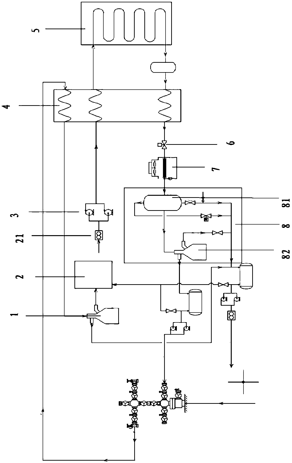
[0030] This embodiment provides a heavy oil fission viscosity reduction treatment device, please refer to figure 1 , the device includes:

[0031] Centrifuge 1, the centrifuge 1 receives the mixed liquid from the mixed liquid in the well, and separates the mixed liquid from oil and water to obtain crude oil and water; the centrifuge 1 also includes: a vertical shaft; a drum, the rotating drum The drum is connected to the upper end of the vertical shaft and is driven to rotate by a motor through a transmission device; the feeding pipe is located at the center of the drum; the disc is located inside the drum and is connected to the feeding pipe The lower end is connected to expand the deposition area of ​​the drum. The discs are stacked with each other with gaps, and the number of the discs is at least two.

[0032] Specifically, according to the water content analysis of the crude oil sampled from the No. 2 Oil Production Plant of Tahe Oilfield, the test results show that the...

Embodiment 2

[0054] This embodiment provides a fission viscosity reduction treatment method for heavy oil. The mixed solution (95° C.) is advanced into the centrifuge 1 to separate 10% water contained in the mixed solution. This part of the water has a high degree of mineralization. If it is not separated, the salt in the water will form salt scale inside the pipeline and the inner wall of the heating furnace tube, which will block the pipeline, make the heating furnace unable to exchange heat, and eventually lead to system failure. The crude oil after separation is about 19t / d, and enters the buffer tank 2 for buffering. The buffer tank 2 is equipped with a liquid level gauge display, and the front end is equipped with automatic drip irrigation. The function of the buffer tank 2 is to buffer incoming crude oil to prevent the booster pump 3 from being sucked up due to large flow changes. Then the crude oil enters the booster pump 3 to pressurize to 10-25MPa and then is heated to 345°C by t...


PUM

PropertyMeasurementUnit
viscosityaaaaaaaaaa

Abstract

The invention discloses a viscous oil fission viscosity reduction treatment device, and belongs to the field of oil exploitation. In-well mixed liquid is received by a centrifugal machine, oil-water separation is performed for the mixed liquid, viscous oil from the centrifugal machine is received by a buffer tank and injected into a booster pump and boosted, the viscous oil is heated through a high-temperature heat exchanger, pyrolysis, fission and viscosity reduction of the viscous oil are performed by a pyrolysis and fission furnace, so that the viscous oil from the pyrolysis and fission furnace is received by a pressure reduction device, pressure reduction is performed for the viscous oil, the viscous oil from the pressure reduction device is received by an air cooling tower and cooled, and the viscous oil from the air cooling tower is received by a separator and separated to obtain heavy oil and non-congealable oil. The treatment device solves the technical problems that part wells do not have thin oil to blend and production benefits are poor as thin oil blending cost is high in the prior art.

Description

technical field [0001] The invention relates to the field of petroleum exploitation, in particular to a heavy oil fission viscosity reduction treatment device. Background technique [0002] As a major energy source, oil consumes a lot. However, due to the different viscosity of crude oil directly extracted from the well, and the lack of thin oil resources, it cannot meet the demand for use. Therefore, it is necessary to process heavy oil to reduce the viscosity to meet the needs of use. need. [0003] The main solution in the prior art is to use thin oil and heavy oil to mix according to a certain ratio, so as to reduce the viscosity of the heavy oil. [0004] However, in the process of realizing the technical solution of the invention in the embodiment of the present application, the inventor of the present application found that the above-mentioned technology has at least the following technical problems: [0005] The viscosity reduction method in the prior art has the t...

Claims


Application Information

Patent Timeline
Patent Type & Authority Patents(China)
IPC IPC(8): C10G55/04
CPCC10G55/04C10G2300/1033C10G2300/202C10G2300/206C10G2300/302
Inventor 杜宝华
Owner 艾斯韦尔工程技术服务(北京)有限公司
Why Eureka
Try Eureka