Spiral shaft type separating machine for filament and staple fibers

A technology of fiber separator and screw shaft, which is applied in fiber separation, fiber treatment, textiles and papermaking, etc. It can solve the problems of poor dust removal effect, achieve the effect of enlarged space, long spindle and high production capacity

Inactive Publication Date: 2017-06-30
林雁 +2
View PDF8 Cites 1 Cited by
  • Summary
  • Abstract
  • Description
  • Claims
  • Application Information

AI Technical Summary

Problems solved by technology

The working principle of these two typical devices is the same. The efficiency of dust removal depends on the stagnation time of fibers in space, but the dust removal effect is not good due to the limitation of output.

Method used


Image

  • Spiral shaft type separating machine for filament and staple fibers
  • Spiral shaft type separating machine for filament and staple fibers
  • Spiral shaft type separating machine for filament and staple fibers

Examples


Embodiment Construction

[0026] The present invention is described in detail below in conjunction with accompanying drawing and embodiment, and wherein accompanying drawing constitutes a part of this application, but those skilled in the art should know that the following embodiment is not the only limitation that the technical scheme of the present invention is done, Any equivalent transformation or modification made under the spirit of the scheme shall be deemed to belong to the protection scope of the present invention.

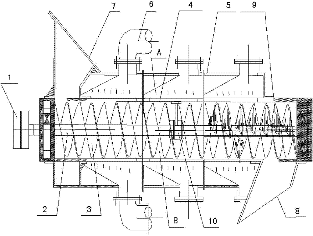
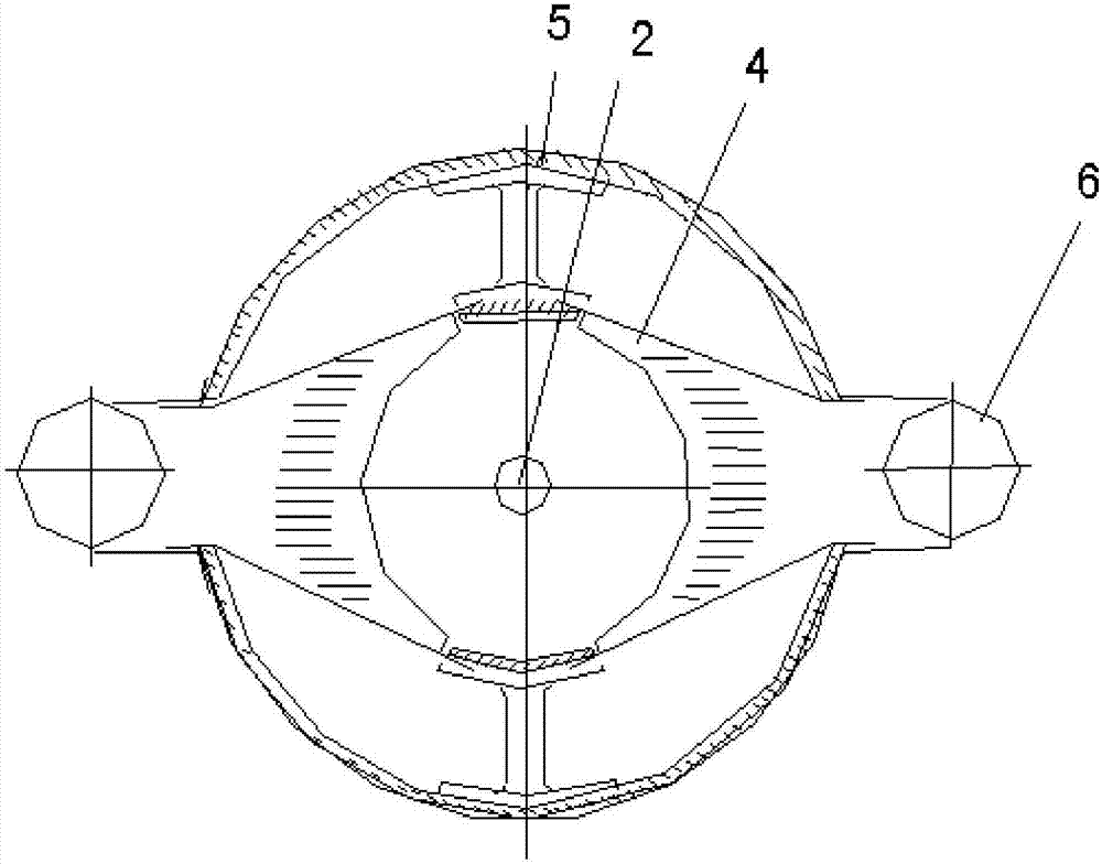
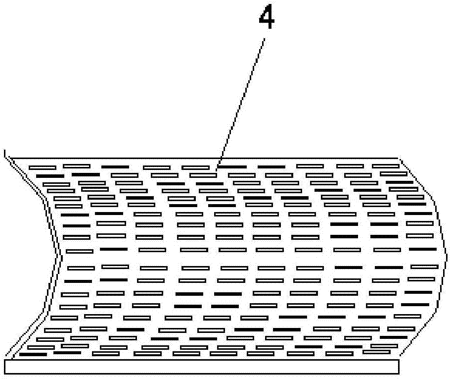
[0027] Such as figure 1 , figure 2 As shown, the machine consists of motor 1, main shaft 2, screw blade 3, screen cylinder 4, host casing 5, negative pressure tube 6, feed hopper 7, discharge hopper 8 and other main components. The main body of the device is constructed of metal.

[0028] The motor 1 is connected to the main shaft 2 through a coupling, the main shaft 2 is supported by the frame and placed in the screen cylinder 4, and the helical blade 3 is installed on the mai...


PUM


Abstract

The invention discloses a spiral shaft type separating machine for filament and staple fibers. The machine comprises a machine frame, a motor, a main shaft, a spiral blade and a mainframe shell, wherein a cylindrical screen is fixed at the periphery of the spiral blade and the main shaft, a material mainstream passage is formed in the cylindrical screen, a negative pressure chamber is formed between the cylindrical screen and the mainframe shell and is arranged continuously in a sectionalized manner, and filter screens are arranged by grade along a material conveying direction; the spiral blade consists of two spiral blades, and hand grips are arranged on surfaces of the spiral blades. Supporting roller guide rails are arranged on the internal wall of the cylindrical screen, supporting roller components are correspondingly arranged on the spiral blades and comprise steel balls embedded in the supporting roller guide rails, and the problem in stability of a long shaft is solved by symmetrical fulcrums. According to the spiral shaft type separating machine for the filament and staple fibers, by adopting a spiral type long shaft conveying scheme, the vacancy in large-scale fiber separation in the field of textiles is filled up.

Description

technical field [0001] The invention relates to textile fiber processing equipment, in particular to a spiral long-axis long-short fiber separator. Background technique [0002] In textile technology and textile engineering equipment, there are not many special equipment and technologies for separating long and short textile fibers. The existing separation equipment for long and short cotton textile fibers only has textile bomb cleaning machine, Jingwei Textile Machinery JWF1053 type dust removal machine, and FA156 type dust removal machine. The working principle of the bomb cleaning machine is to filter short fibers with a full-hole cylinder. In textile engineering, the full-hole cylinder is commonly called a dust cage. After the textile raw materials are opened, they enter the surface of the dust cage cylinder of the bomb cleaning machine. The direction rotates with the axis, and the inner cylinder of each dust cage is set as a negative pressure air system. When the texti...

Claims


Application Information

Patent Timeline
Patent Type & Authority Applications(China)
IPC IPC(8): D01G5/00
CPCD01G5/00
Inventor 林雁高尚友康建鹏
Owner 林雁
Why Eureka
Try Eureka