Special measurer for building design

An architectural design, measuring instrument technology, applied in the direction of measuring devices, height/level measurement, instruments, etc., can solve the problems that affect the designer's project progress, difficulty, and limitations of measuring instruments, etc., to achieve simple structure, easy to use and read , multi-functional effect

Inactive Publication Date: 2017-06-30
QINGDAO XINYIFA IND & TRADE
0 Cites 0 Cited by

AI-Extracted Technical Summary

Problems solved by technology

[0002] In construction engineering, it is difficult to measure the height of a building with steps, and when the height of t...

Method used

Please refer to Fig. 1~2, in the embodiment of the present invention, a kind of special measurer for architectural design, comprises secondary ruler post 1, clamping part 2, laser range finder 3, main ruler post 4, protractor 5, slide Groove 6, angle indication scale 7, height indication scale 8, sight hole 9, alignment tip 10, fastening knob 11, adjustment bolt 12, length indication scale 13, level bar 14 and spirit level 15, said level bar 14 The lower side of the side is provided with a length indicator scale 13, which is convenient for engineering length measurement by the length indicator scale 13, and the left and right ends of the horizontal ruler column 14 are provided with adjusting bolts 12, and the right upper part of the horizontal ruler column 14 is provided with There is a spirit level 15, through which the level gauge 15 cooperates with the adjustment bolt 12 to adjust the levelness of the horizontal ruler column 14, to improve the accuracy of measurement, the left side of the spirit level 15 is vertically provided with the main ruler column 4 on the top of the horizontal ruler column 14 , the middle part of the main ruler column 4 is hinged with an auxiliary ruler column 1, and the hinge point of the auxiliary ruler column 1 and the main ruler column 4 is located in the middle part of the auxiliary ruler column 1, and the right side end of the auxiliary ruler column 1 is front The side is hinged by a rotating shaft 21 and is provided with a clamping piece 2. The clamping piece 2 is a cross-shaped structure. Through the clamping piece 2, the building to be measured is clamped for height measurement. The right end of the auxiliary ruler column 1 The rear side is provided with a laser range finder 3, through which the height of the distant object is measured, and through conversion, the specific height data is obtained. Slidingly connected in the middle chute 6 of the protractor 5, the position of the auxiliary ruler column 1 can be fixed by the fastening knob 11, and the left side of the fastening knob 11 is provided with an alignment tip at the end of the auxiliary ruler column 1 10. By aligning the tip 10, it is convenient to read the indicated value of the angle indication scale 7. The right side of the fastening knob 11 is provided with a viewing hole 9 on the secondary ruler column 1. The viewing hole 9 is rectangular, and the viewing hole The central position of 9 is provided with a reference line (not shown) parallel to the auxiliary rule...

Abstract

The invention discloses a special measuring device for architectural design, which comprises an auxiliary ruler column, a main ruler column, a protractor and a horizontal ruler column. Both ends of the horizontal ruler column are provided with adjusting bolts, and the right side of the horizontal ruler column is The upper part is provided with a spirit level, and the left side of the spirit level is vertically provided with a main ruler column on the top of the horizontal ruler column. Hinged by the rotating shaft, there is a clamping piece, a laser rangefinder is provided on the rear side of the right end of the auxiliary ruler column, and the left end of the auxiliary ruler column is slidably connected to the middle chute of the protractor through a fastening knob Inside, the protractor is vertically located on the left side of the main ruler column. The invention has the advantages of simple structure, various functions, wide measurement range, convenient use and reading, and brings help to architectural designers.

Application Domain

Height/levelling measurement

Technology Topic

Laser rangingLaser rangefinder +3

Image

  • Special measurer for building design
  • Special measurer for building design

Examples

  • Experimental program(1)

Example Embodiment

[0013] The technical solutions in the embodiments of the present invention will be clearly and completely described below in conjunction with the accompanying drawings in the embodiments of the present invention. Obviously, the described embodiments are only a part of the embodiments of the present invention, rather than all the embodiments. Based on the embodiments of the present invention, all other embodiments obtained by those of ordinary skill in the art without creative work shall fall within the protection scope of the present invention.
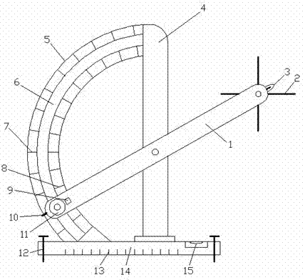
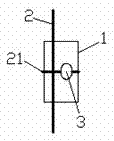
[0014] See Figure 1~2 , In the embodiment of the present invention, a special measuring instrument for architectural design includes a secondary ruler column 1, a clamping piece 2, a laser rangefinder 3, a main ruler column 4, a protractor 5, a chute 6, an angle indicating scale 7, a height Indicating scale 8, sight hole 9, aligning tip 10, tightening knob 11, adjusting bolt 12, length indicating scale 13, leveling ruler column 14 and spirit level 15, the side of the leveling ruler column 14 is provided with a length indicating scale on the lower side 13. The length indicator scale 13 is used to facilitate engineering length measurement. Both the left and right ends of the level column 14 are provided with adjusting bolts 12, and the upper right part of the level column 14 is provided with a level 15 which is adjusted by the level 15 The bolt 12 cooperates to adjust the levelness of the horizontal ruler column 14 to improve the accuracy of measurement. The left side of the leveler 15 is vertically provided with a main ruler column 4 on the upper part of the horizontal ruler column 14, and the middle part of the main ruler column 4 A secondary ruler column 1 is hingedly connected, and the hinge point of the secondary ruler column 1 and the main ruler column 4 is located in the middle of the secondary ruler column 1, and the front side of the right end of the secondary ruler column 1 is hinged with a clamping connection through a shaft 21 Part 2. The clamping part 2 is a cross-shaped structure. The clamping part 2 is used to measure the height of the building to be measured. A laser rangefinder 3 is provided on the back of the right end of the secondary ruler column 1. , The height of the long-distance object is measured by the laser rangefinder 3, and the specific height data is obtained through conversion. The left end of the secondary ruler column 1 is slidably connected to the middle chute of the protractor 5 through the tightening knob 11 In 6, the position of the secondary ruler column 1 can be fixed by tightening the knob 11. The left side of the tightening knob 11 is provided with an alignment tip 10 at the end of the secondary ruler column 1. The alignment tip 10 is convenient for reading Take the indicated value of the angle indicating scale 7. The right side of the tightening knob 11 is provided with a viewing hole 9 on the secondary ruler column 1. The viewing hole 9 is rectangular, and the center position of the viewing hole 9 is the same as that of the secondary ruler column 1. A reference line (not shown) is provided in parallel, and the reference line on the sight hole 9 is convenient to read the indicated value of the height indication scale 8. The protractor 5 is vertically located on the left side of the main ruler column 4, and the protractor 5 The top is connected to the main ruler column 4, the bottom of the protractor 5 is connected to the upper part of the horizontal ruler column 14, the middle position of the protractor 5 is provided with a chute 6, and the arc radius of the chute 6 is the auxiliary ruler column 1. The angle indicator scale 7 is provided on the outer ring of the protractor 5, the height indicator scale 8 is provided on the inner ring of the protractor 5, the position of the angle indicator scale 7 and the height indicator scale 8 Correspondingly, after calibration, mark the height of the right end of the sub-ruler column 1 at each angle position of the protractor 5, and then the project height can be measured.
[0015] The working principle of the present invention is: after the instrument is calibrated, the length can be measured by the length indicating scale 13 on the lower side of the horizontal ruler column 14, and the angle can be measured by the angle indicating scale 7 of the outer ring of the protractor 5, and by rotating the auxiliary ruler column 1. , Clamp the rotatable clip 2 to the building design of the height to be measured, and then lock it by tightening the knob 11, and the height indicated by the height indication scale 8 can be read through the reference line in the sight hole 9 The value is the building height. You can read the angle value indicated by the angle indicator scale 7 by aligning the tip 10 with the assistance. When the building height exceeds the measurement range, turn on the laser rangefinder 3 and rotate the auxiliary ruler column 1. , Make the laser rangefinder 3 point to the top of the building, and lock the secondary ruler column 1 by tightening the knob 11. The value read by the laser rangefinder 3 plus the length of the secondary ruler column 1 itself, and the secondary ruler The angle of the rotation of column 1 can be used to obtain the height of the building by the law of sine in the triangle. In addition, adjusting bolts 12 are set at both ends of the level column 14 and a spirit level is set on the upper right side of the level column 14 15. The levelness of the leveling rod 14 can be adjusted to make the height measurement more accurate.
[0016] For those skilled in the art, it is obvious that the present invention is not limited to the details of the foregoing exemplary embodiments, and the present invention can be implemented in other specific forms without departing from the spirit or basic characteristics of the present invention. Therefore, from any point of view, the embodiments should be regarded as exemplary and non-limiting. The scope of the present invention is defined by the appended claims rather than the above description, and therefore it is intended to fall within the claims. All changes within the meaning and scope of equivalent elements of are included in the present invention. Any reference signs in the claims should not be regarded as limiting the claims involved.
[0017] In addition, it should be understood that although this specification is described in accordance with the implementation manners, not each implementation manner only includes an independent technical solution. This narration in the specification is only for clarity, and those skilled in the art should consider the specification as a whole The technical solutions in the embodiments can also be appropriately combined to form other implementations that can be understood by those skilled in the art.

PUM

no PUM

Description & Claims & Application Information

We can also present the details of the Description, Claims and Application information to help users get a comprehensive understanding of the technical details of the patent, such as background art, summary of invention, brief description of drawings, description of embodiments, and other original content. On the other hand, users can also determine the specific scope of protection of the technology through the list of claims; as well as understand the changes in the life cycle of the technology with the presentation of the patent timeline. Login to view more.

Similar technology patents

Body condition measuring device

InactiveUS20050234351A1simple structure
Owner:DENSO CORP

Magnetic cooling apparatus and control method thereof

ActiveUS20130180263A1simple structure
Owner:SAMSUNG ELECTRONICS CO LTD

Dual-Drivetrain of Power-Assist Vehicle

InactiveUS20100181130A1enhance uphill momentumsimple structure
Owner:CHOU WEN CHENG

Classification and recommendation of technical efficacy words

  • Simple structure
  • Versatile

Sharing system for air-conditioning coat

InactiveCN107440179ASimple structureeasy to wear
Owner:QINGDAO HAIER AIR CONDITIONER GENERAL CORP LTD

Feeding device of sorter of batteries plate

InactiveCN101357717ASimple structurecooperate well
Owner:NANJING NORMAL UNIVERSITY

Emergency parachuting device and method for multiple-rotor unmanned aerial vehicle

InactiveCN103895870Aavoid aircraft crashSimple structure
Owner:SOUTH CHINA AGRI UNIV +1

Automobile electric control unit calibration system and method based on ASAP standard

InactiveCN101334662AVersatileResolve interface mismatch
Owner:CHONGQING UNIV OF POSTS & TELECOMM

Multi-bus automobile communication control module based on TCN

ActiveCN1889494AaccelerateVersatile
Owner:ZHUZHOU CSR TIMES ELECTRIC CO LTD

Double on-site bus interface converter

InactiveCN101345629AStrong flexibilityVersatile
Owner:WUHAN UNIV OF SCI & TECH

Enterprise collaborative office management system

InactiveCN105139181AVersatileeasy to operate
Owner:SUZHOU LANGJIETONG INTELLIGENT TECH
Why Eureka
Try Eureka