High and low temperature test device for IC testing

A test device, high and low temperature technology, applied in the direction of electronic circuit testing, etc., can solve the problems of interrupting the high and low temperature test process, and achieve the effect of reducing IC damage and cost

Inactive Publication Date: 2017-06-30
张家港市欧微自动化研发有限公司
View PDF9 Cites 9 Cited by
  • Summary
  • Abstract
  • Description
  • Claims
  • Application Information

AI Technical Summary

Problems solved by technology

[0004] The invention solves the technical problem in the prior art that the high and low temperature box must be opened to

Method used


Image

  • High and low temperature test device for IC testing
  • High and low temperature test device for IC testing

Examples


Embodiment 1

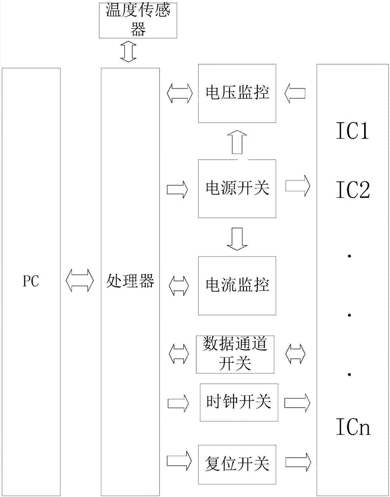
[0043] This embodiment provides a high and low temperature test device applied to IC testing, the high and low temperature test device includes a host computer, the host computer is a PC computer, a hardware circuit connected to the host computer, and a plurality of ICs connected to the hardware circuit The hardware circuit includes a processor, the processor is an ARM processor, a power module connected in parallel with the processor, a current monitoring module, a voltage monitoring module and a switch module; the upper computer is connected and communicated with the ARM processor The processor is used to control the power module, current monitoring module, voltage monitoring module and switch module; the power module is also connected to the voltage monitoring module and the current detection module; the voltage monitoring module is used to detect the IC working voltage; the current detection module is used to detect the working current of the IC; the temperature sensor is u...

Embodiment 2

[0057] On the basis of Embodiment 1, the present embodiment further illustrates the optimization of the correction switch reset correction times, and step (6) is as follows:

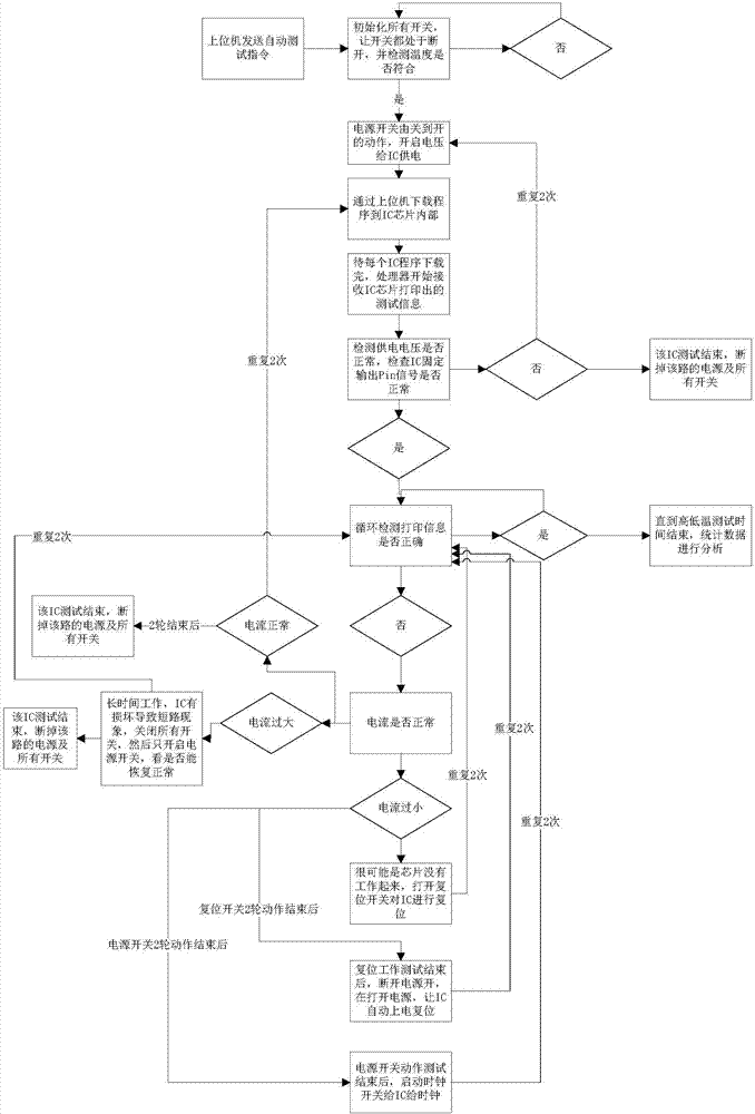
[0058] To repair the abnormality, first check the working current of the abnormal IC through the current monitoring module. After the current is too large to be corrected, the cycle detection and printing information are carried out to check whether the correction is successful;

[0059] If the current is too small, correct the current too small, including turning on the reset switch to perform switch reset correction. After correction, check whether the correction is successful by cyclically detecting and printing information. Switch reset and correct 3 times. The correction is successful; if it is not successful, perform 3 power-on reset corrections by turning off and on the power module. After each power-on reset correction, turn on the clock switch to give the IC a clock signal. After the IC receives...

Embodiment 3

[0061] On the basis of Embodiment 1, the present embodiment further illustrates the optimization of the correction switch reset correction times, and step (6) is as follows:

[0062] To repair the abnormality, first check the working current of the abnormal IC through the current monitoring module. After the current is too large to be corrected, the cycle detection and printing information are carried out to check whether the correction is successful;

[0063] If the current is too small, correct the current too small, including turning on the reset switch to perform switch reset correction. After correction, check the printing information to check whether the correction is successful. The switch resets and corrects 5 times. The correction is successful; if it is not successful, perform 5 power-on reset corrections by turning off and on the power module. After each power-on reset correction, turn on the clock switch to give the IC a clock signal. After the IC receives the cloc...


PUM


Abstract

The invention relates to a high and low temperature test device for IC testing, so that technical problems that abnormity elimination and correction can not be carried out on a single abnormal integrated circuit while a high-and-low-temperature box is not opened and the power of the integrated circuit that can not be corrected or has been tested can not be cut off completely to enter a silence state in the prior art can be solved. The test device is composed an upper computer, a hardware circuit connected with the upper computer, and a plurality of ICs connected with the hardware circuit. The hardware circuit includes a processor, a power supply module, a current monitoring module, a voltage monitoring module and a switch module, wherein the power supply module, the current monitoring module, the voltage monitoring module and the switch module are connected with the processor. Therefore, the problems can be solved well. The test device can be applied to the industrial IC production.

Description

technical field [0001] The invention relates to the field of integrated circuit testing, in particular to a working method of a high and low temperature testing device applied to IC testing. Background technique [0002] Integrated circuits, referred to as ICs, must undergo electrical performance tests at different temperatures before entering the market to simulate the temperature stress of integrated circuits under different working conditions. The high temperature is generally 120°C and the low temperature is -40°C. The problem of high and low temperature testing is an old problem in the testing of integrated circuits. [0003] The existing high and low temperature testing method is to carry out signal processing and testing outside the high and low temperature box after a single integrated circuit is connected. Existing high and low temperature test devices and methods cannot check and correct a single abnormal integrated circuit without opening the high and low tempera...

Claims


Application Information

Patent Timeline
IPC IPC(8): G01R31/28
Inventor 不公告发明人
Owner 张家港市欧微自动化研发有限公司
Why Eureka
Try Eureka