Device for generating plasma photonic crystals with different gas temperatures
A plasma and photonic crystal technology, applied in the field of plasma application technology and optics, to achieve wide application prospects and increase the effect of selection methods
- Summary
- Abstract
- Description
- Claims
- Application Information
AI Technical Summary
Problems solved by technology
Method used
Image

Examples
Embodiment 1
[0022] Embodiment 1, a device for generating plasma photonic crystals with different gas temperatures.
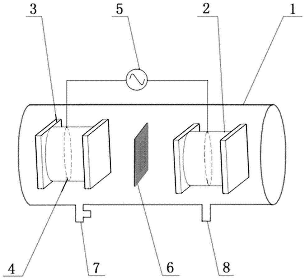
[0023] Such as figure 1 As shown, the device for generating plasma photonic crystals with different gas temperatures provided by the present invention is specifically: two airtight dielectric containers are symmetrically arranged in a horizontal cylindrical vacuum reaction chamber 1, and water is injected into the airtight dielectric container. A water electrode 2 with two polar plates facing each other is formed. The two water electrodes 2 are electrically connected with the plasma generating power source 5 outside the vacuum reaction chamber 1 . In this embodiment, the water electrode 2 is made of a plexiglass tube sealed by glass baffles 3 at both ends, the plexiglass tube is filled with water, and a copper ring 4 is set in the plexiglass tube. The two copper rings 4 are respectively electrically connected to the positive pole and the negative pole of the plasma genera...
Embodiment 2
[0030] combine figure 1 and figure 2, a vacuum reaction chamber 1 is set, an air inlet 7 and an air outlet 8 are opened on the wall of the vacuum reaction chamber 1, and two water electrodes 2 opposite to each other are installed in the vacuum reaction chamber 1. The water electrode 2 is composed of a plexiglass tube sealed with glass baffles 3 on both sides and filled with water, and a built-in copper ring 4 is electrically connected to the plasma generating power supply 5 outside the vacuum reaction chamber 1 .
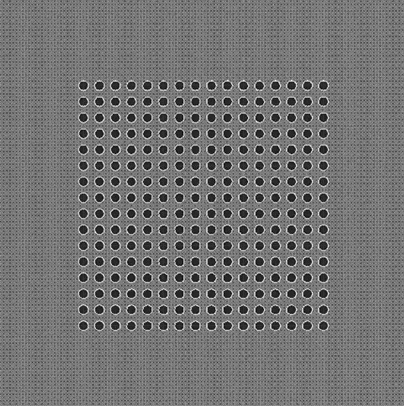
[0031] A solid frame 6 with a thickness of 1mm is arranged between the two water electrodes 2. The solid frame 6 is made of resin material, and its plane is perpendicular to the axes of the two water electrodes 2, and the two sides are close to the two water electrodes 2. end face. 16*16 circular through holes with a diameter of 1mm are opened in the inner area of the solid frame 6, and the minimum distance between adjacent through holes is 1mm. The area of ...
Embodiment 3
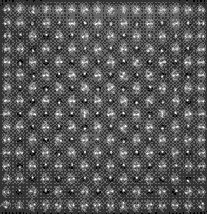
[0035] Compared with Embodiment 2, this embodiment differs in that the discharge gas is a mixture of air and argon, the volume content of argon is 30%, and the voltage amplitude is 2.72kV. When the switch is closed, the plasma generating power supply 5 acts on the two water electrodes 2, which can generate alternating single and double point plasma luminescent patterns, such as Figure 6 shown. Figure 6 and image 3 Similarly, except for the outermost circle of plasma luminescence patterns, the internal plasma luminescence patterns present an alternate arrangement of single and double points, that is, the plasma in two adjacent through holes (or pores) The structure of the luminescent pattern is different, one is a single discharge wire (corresponding to a single-point structure), and the other is two bundles of discharge wires (corresponding to a double-point structure).
[0036] Collect the rotation spectra of nitrogen molecular ions in two adjacent through holes during d...
PUM
| Property | Measurement | Unit |
|---|---|---|
| thickness | aaaaa | aaaaa |
| thickness | aaaaa | aaaaa |
| thickness | aaaaa | aaaaa |
Abstract
Description
Claims
Application Information
 - R&D
- Intellectual Property
- Life Sciences
- Materials
- Tech Scout
- Unparalleled Data Quality
- Higher Quality Content
- 60% Fewer Hallucinations
Browse by: Latest US Patents, China's latest patents, Technical Efficacy Thesaurus, Application Domain, Technology Topic, Popular Technical Reports.
© 2025 PatSnap. All rights reserved.Legal|Privacy policy|Modern Slavery Act Transparency Statement|Sitemap|About US| Contact US: help@patsnap.com