Fastening and disassembling device for lens clamping ring

A disassembly device and fastening technology, which is applied in the field of loading and unloading of aerospace lens rings, can solve the problems of lens surface scratches, inability to meet the size requirements of ring fastening and disassembly, and unstable working effects, etc., and achieve the effect of convenient use

Active Publication Date: 2017-06-30
XI'AN INST OF OPTICS & FINE MECHANICS - CHINESE ACAD OF SCI
View PDF21 Cites 5 Cited by
  • Summary
  • Abstract
  • Description
  • Claims
  • Application Information

AI Technical Summary

Problems solved by technology

[0003] The object of the present invention is to provide a fastening and dismounting device for the lens clamping ring, which is used to solve the problem that the ordinary wrench in the prior art cannot meet the size requirements for fastening and dismounting the clamping ring, the working effect is not stable enough, and it is easy to cause The problem of scratches on the lens surface

Method used


Image

  • Fastening and disassembling device for lens clamping ring
  • Fastening and disassembling device for lens clamping ring

Examples


Embodiment Construction

[0016] The present invention will be described in detail below in conjunction with specific embodiments and accompanying drawings.

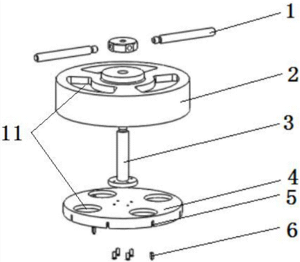
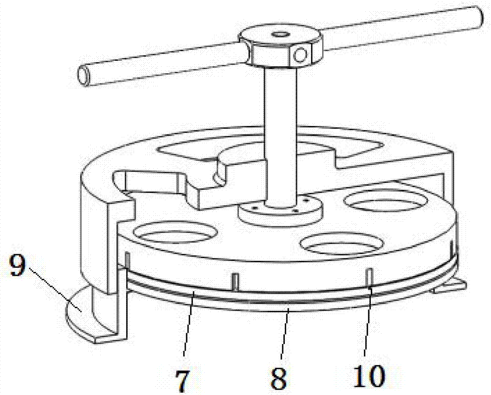
[0017] Such as figure 1 As shown, the embodiment provides a fastening and dismounting device for the lens clamping ring, including a rotating handle 1, a torsion bar 3, a clamping ring chuck 4, a positioning sleeve 2 and a card 6, and the rotating handle 1 is connected with the torsion bar 3 The middle part of the pressure ring chuck 4 is fixedly connected, and the positioning sleeve 2 is set on the torsion bar 3 and is located between the rotary handle 1 and the pressure ring chuck 4. Eight card slots 5 are set, and cards 6 are arranged in the card slots 5 . In order to better coaxially position the ring chuck 4 and the frame 9 , the positioning sleeve 2 is in the shape of a bottle cap, and the inner diameter of the positioning sleeve 2 is larger than the outer diameter of the ring chuck 4 . In order to facilitate the real-time observation of ...


PUM


Abstract

The invention belongs to the field of spaceflight lens clamping ring loading and unloading, and particularly relates to a fastening and disassembling device for a lens clamping ring. The problems that an ordinary wrench cannot meet the size requirement of the fastening and disassembling of the clamping ring; the work effect is not stable enough; and the lens surface is easily scratched in the prior art are solved. The device comprises a rotary handle, a torsion bar, a clamping ring chuck, a positioning sleeve and cards. The rotary handle is fixedly connected with the middle part of the clamping ring chuck through the torsion bar. The positioning sleeve sleeves the torsion bar and is located between the rotary handle and the clamping ring chuck. The inner wall of the positioning sleeve matches the outer wall of a frame. At least two card slots are arranged in the outer periphery of the clamping ring chuck, and the cards are arranged in the card slots.

Description

technical field [0001] The invention belongs to the field of assembly and disassembly of aerospace lens rings, in particular to a fastening and dismounting device for lens rings. Background technique [0002] At present, the lens diameter of ultra-high-precision aerospace lenses is relatively large, and ordinary wrenches cannot meet the size requirements for fastening and dismounting of the pressure ring. At the same time, optical glass has very high requirements for preventing scratches. In the middle, it is easy to cause scratches on the surface of the lens. The Chinese patent with publication number 203311070U (publication date: 2013-11-27) solves the multi-size adaptation problem in the working condition through the movable clamping plate, but it cannot guarantee stable rotation and non-slip during the working process, and still exists Risk of scratching the lenses. Contents of the invention [0003] The object of the present invention is to provide a fastening and d...

Claims


Application Information

Patent Timeline
Patent Type & Authority Applications(China)
IPC IPC(8): G02B7/02
CPCG02B7/02
Inventor 耿波牛源段战军张鸽曹明强
Owner XI'AN INST OF OPTICS & FINE MECHANICS - CHINESE ACAD OF SCI
Why Eureka
Try Eureka