Measuring device and measuring method for stitching interference of planar sub-aperture

A technology of sub-aperture splicing and sub-aperture, applied in measurement devices, optical devices, instruments, etc., can solve the problems of coma aberration of detection results, measurement errors, affecting the measurement accuracy of a single sub-aperture, and reduce the deviation between the actual position and the ideal position. , Improve the measurement accuracy and realize the effect of automatic measurement

Active Publication Date: 2017-07-04
SHANGHAI INST OF OPTICS & FINE MECHANICS CHINESE ACAD OF SCI
View PDF6 Cites 13 Cited by
  • Summary
  • Abstract
  • Description
  • Claims
  • Application Information

AI Technical Summary

Problems solved by technology

However, the measurement error of a single sub-aperture will also accumulate during the splicing process, and improving the detection accuracy of a single sub-aperture is a prerequisite for achieving high-precision splicing
For the sub-aperture splicing measurement system, the measurement accuracy of a single sub-aperture will be affected by various factors such as the number of interference fringes caused by the pitch and yaw error of the splicing stage, the change of the splicing position, and the standard mirror shape. For example, when the interference fringes In many cases, due to the influence of the return error of the interferometer, coma aberration will be introduced into the detection results of the single sub-aperture; due to the pitch and yaw of the spliced ​​stage, the splicing position of the single sub-aperture will deviate from the ideal splicing position, and the measurement result will be introduced. error
These error factors are not considered in the existing splicing detection technology, which affects the measurement accuracy of a single sub-aperture. Improving the splicing measurement accuracy of a single sub-aperture requires the combination of the structure of the splicing measurement device and the measurement method.

Method used


Image

  • Measuring device and measuring method for stitching interference of planar sub-aperture
  • Measuring device and measuring method for stitching interference of planar sub-aperture

Examples


Embodiment Construction

[0030] In order to better understand the purpose, technical solutions and advantages of the present invention, the present invention will be further described below in conjunction with the accompanying drawings and embodiments, but the protection scope of the present invention should not be limited thereby.

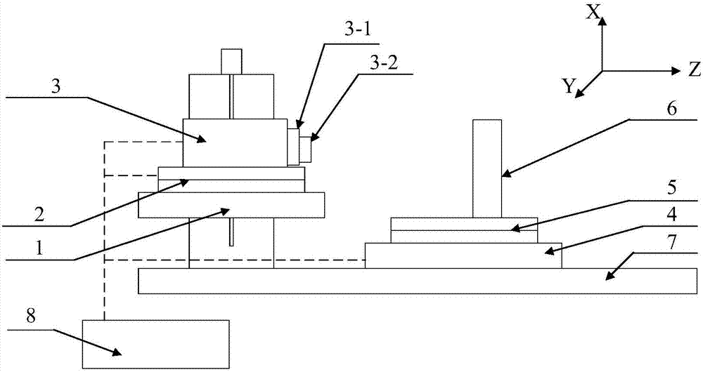
[0031] A planar surface-shaped sub-aperture splicing interference detection device, such as figure 1 As shown, it includes: interferometer 3, interferometer splicing translation platform 1, interferometer tilt adjustment platform 2, DUT splicing translation platform 4, DUT tilt adjustment platform 5, DUT 6, support platform 7, and control System 8;

[0032] Described interferometer 3 is the DynaFiz interferometer of U.S. Zygo Company, and measuring diameter is 100mm;

[0033] Described interferometer 3 comprises plane standard mirror 3-2 and standard mirror tilt adjustment frame 3-1; The reference plane place plane of described plane standard mirror 3-2 is the XY plane, ...


PUM


Abstract

The invention provides a measuring device and a measuring method for stitching interference of a planar sub-aperture. The measuring device comprises an interferometer, an interferometer splicing displacement table, an interferometer inclination adjusting platform, a measured member splicing displacement platform, a measured member inclination adjusting platform, a measured member, a supporting platform and a control system. The measuring device and the measuring method have advantages of high sub-aperture positioning precision, high measurement precision and full automatic measurement.

Description

technical field [0001] The invention relates to the field of plane shape interferometry, in particular to a plane shape sub-aperture splicing interferometry device and measurement method. Background technique [0002] The sub-aperture splicing interferometry technology can realize the measurement of large-aperture optical components at low cost, while retaining the high spatial resolution and high precision of small-aperture measurement. In 1982, C.J.Kim of the Optical Center of the University of Arizona in the United States first proposed the concept of subaperture splicing interferometry (1. [C.Kim, J.Wyant. Subaperture test of a large flator a fast aspheric surface[J].Opt.Soc.Am ., 1981, 71:1587]). In 1985, T.W.Stuhlinger proposed the discrete phase method, using the optical phase measurements of a large number of discrete points distributed on the sub-aperture to describe the wavefront. This idea is a new milestone in the development of sub-aperture testing and the prot...

Claims


Application Information

Patent Timeline
Patent Type & Authority Applications(China)
IPC IPC(8): G01B11/24
CPCG01B11/2441
Inventor 唐锋卢云君郭福东王向朝张国先
Owner SHANGHAI INST OF OPTICS & FINE MECHANICS CHINESE ACAD OF SCI
Why Eureka
Try Eureka