
An integrated alignment and calibration system

An integrated, box-shaped technology, which is applied in the direction of microlithography exposure equipment, instruments, photoplate making process of pattern surface, etc., can solve the problem that the processing accuracy and motion accuracy cannot be absolutely accurate, and the relative position of CCD camera and suction cup camera Inaccurate, inaccurate graphic exposure and other problems, to achieve the effect of improving calibration work efficiency, improving alignment work efficiency, and improving calibration efficiency

Active Publication Date: 2019-01-04
无锡影速半导体科技有限公司
View PDF6 Cites 0 Cited by
  • Summary
  • Abstract
  • Description
  • Claims
  • Application Information

AI Technical Summary

Problems solved by technology

However, in the prior art, two cameras, a CCD camera and a suction cup camera, are used for alignment and calibration respectively. The two cameras can move independently of each other, and their relative positional relationship is in the process of movement. The accuracy cannot be absolutely accurate, which often leads to inaccurate relative positions between the CCD camera and the suction cup camera, which in turn leads to the inaccurate determination of the relative position between the CCD camera and the DMD exposure components and the relationship between different DMD exposure components during calibration. The relative position will eventually lead to inaccurate graphic exposure, and even product scrapping

Method used


Image

  • An integrated alignment and calibration system
  • An integrated alignment and calibration system
  • An integrated alignment and calibration system

Examples


Embodiment 1

[0028] Embodiment 1 Alignment and calibration integrated system

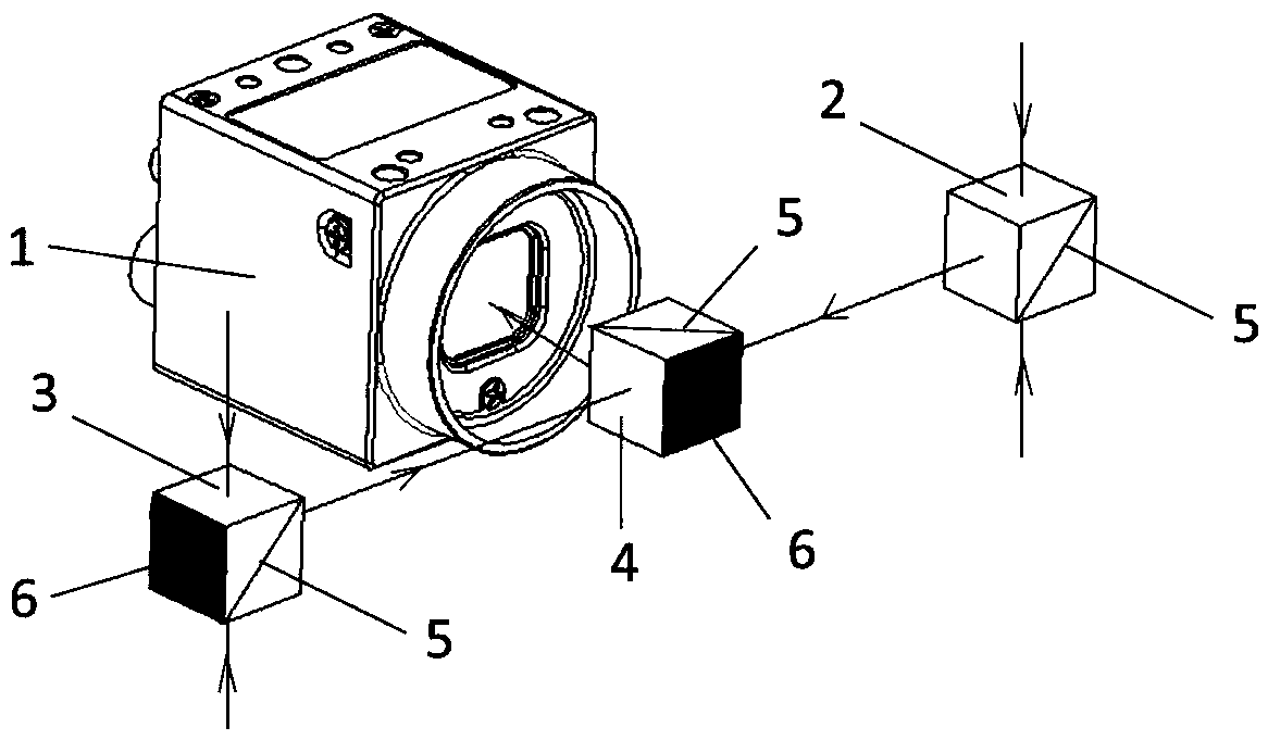
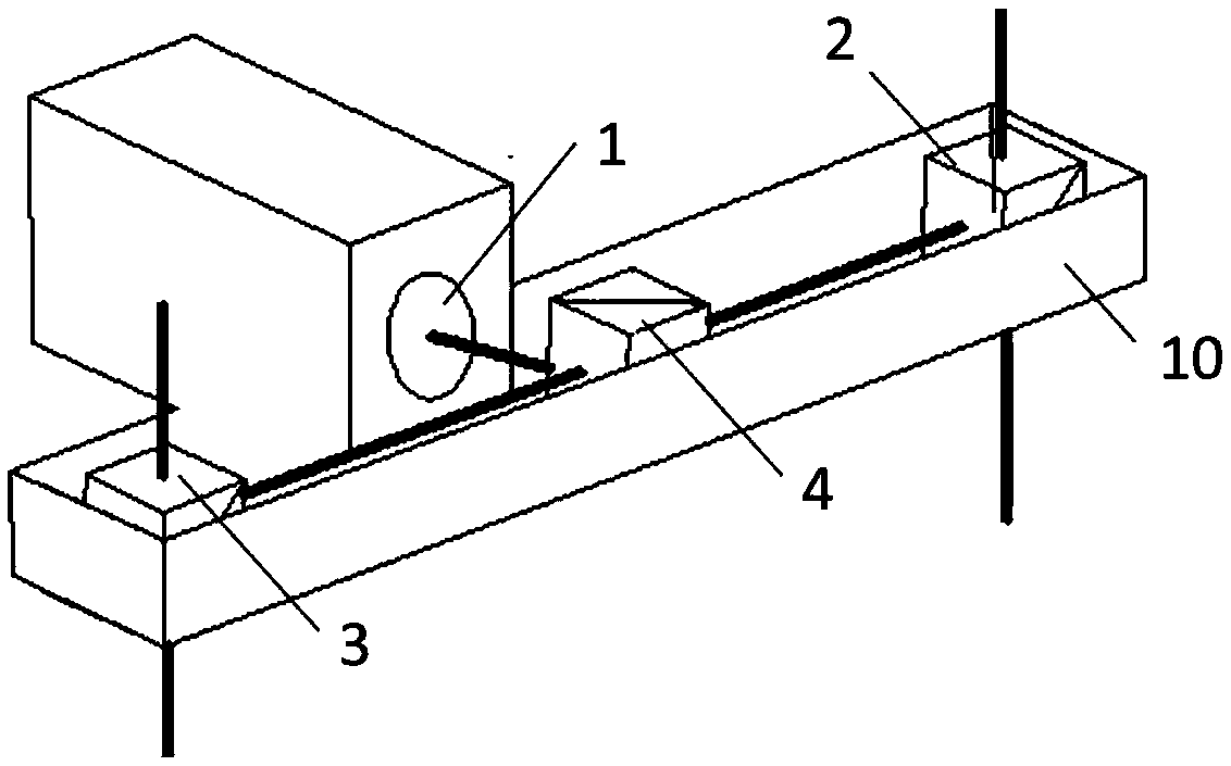
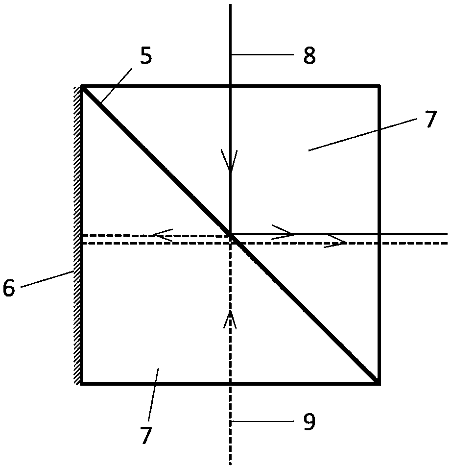
[0029] Such as Figure 1-Figure 4 The alignment and calibration integrated system of the invention is illustrated as shown.

[0030] The alignment and calibration integrated system includes a CCD camera 1 and an optical path assembly. The CCD camera 1 is set horizontally, and the lens of the CCD camera 1 faces the horizontal direction. Prism assembly 4, each group of prism assemblies comprises 2 oppositely arranged triangular prisms 7, and said triangular prism 7 is a triangular prism structure whose cross section is an isosceles right triangle, and the faces where the hypotenuses of 2 triangular prisms 7 of each group of prism assemblies are opposite Close to the setting, a semi-transparent and semi-reflective film 5 is arranged between the two sides; 3 groups of prism assemblies are arranged in a straight line, wherein the middle group of prism assemblies 4 is located directly in front of the lens of the CCD ...


PUM


Abstract

The invention discloses an alignment and calibration integrated system, and belongs to the technical field of a direct-writing exposure machine. The alignment and calibration integrated system comprises a CCD camera and an optical path assembly, wherein the optical path assembly comprises three groups of prism assemblies; each prism assembly comprises two triangular prisms arranged oppositely; and the prisms are provided with semi-transparent and semi-reflective films and total reflective films. By virtue of the alignment and calibration integrated system, the problem of inaccurate alignment and positioning in the prior art is solved; the alignment and calibration working efficiency is improved; and by integrating an alignment optical path and a calibration optical path, equipment is simplified.

Description

technical field [0001] The invention relates to an alignment and calibration integrated system, which belongs to the technical field of direct writing exposure machines. Background technique [0002] When the existing direct writing exposure machine works, two steps of alignment and calibration are required. [0003] The purpose of alignment is to find the position to be exposed on the substrate and accurately transfer the position to the DMD exposure component to ensure the accuracy of exposure. During alignment, the CCD camera captures the positioning holes or other positioning marks on the PCB, accurately records the position coordinates of the positioning holes or positioning marks, and transmits them to the DMD exposure component to complete the alignment. [0004] The purpose of calibration is to detect and determine the accuracy of the relative position between CCD camera and DMD exposure components and the relative position between different DMD exposure components....

Claims


Application Information

Patent Timeline
Patent Type & Authority Patents(China)
IPC IPC(8): G03F7/20G03F9/00
CPCG03F7/70383G03F9/7046G03F9/7076
Inventor 杨文赵华
Owner 无锡影速半导体科技有限公司
Learn More