
Screen package method

A packaging method and screen technology, which is applied in the direction of instruments, semiconductor devices, electrical components, etc., can solve the problems of affecting the yield rate of the screen, affecting the service life of the screen, and poor packaging effect of the screen.

Active Publication Date: 2017-07-04
KUNSHAN GO VISIONOX OPTO ELECTRONICS CO LTD
View PDF5 Cites 4 Cited by
  • Summary
  • Abstract
  • Description
  • Claims
  • Application Information

AI Technical Summary

Problems solved by technology

[0011] The embodiment of the present invention provides a screen packaging method, which is used to solve the problem that in the prior art, the sealing material printed by screen printing technology is prone to missing or air bubbles, resulting in poor screen packaging effect and prone to unsealed screens , affecting the yield rate of the screen produced by this method, and affecting the service life of the screen

Method used


Image

  • Screen package method
  • Screen package method
  • Screen package method

Examples


Embodiment 1

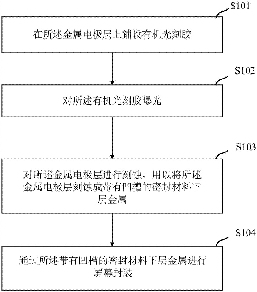
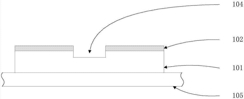
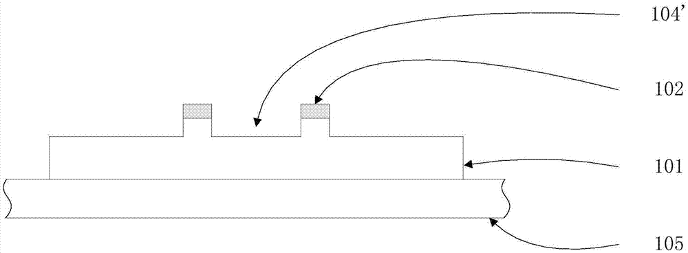
[0040] figure 1 The first screen encapsulation process provided by the embodiment of the present invention, wherein the pre-prepared metal electrode layer 101 is laid on the glass substrate 105, the method provided by the present invention specifically includes the following steps:

[0041] S101 : laying an organic photoresist 102 on the metal electrode layer 101 .

[0042] In the embodiment of the present invention, the metal electrode layer 101 can be etched using the photolithography method in the general screen production process, so the present invention can lay organic photolithography on the pre-prepared metal electrode layer 101. Glue 102.

[0043] For the convenience of subsequent description, in the present invention, the area of ​​the metal electrode layer 101 that needs to be etched into the lower metal layer 103 of the sealing material is referred to as the encapsulation area, that is, the area where the structure used to encapsulate the screen is located during ...

Embodiment 2

[0069] based on figure 1 The same principle, the present invention also provides the second screen encapsulation process, such as Image 6 As shown, wherein the pre-prepared metal electrode layer 101 is laid on the glass substrate 105, the method provided by the present invention specifically includes the following steps:

[0070] S601: laying an inorganic material layer 109 on the metal electrode layer 101 .

[0071] In the embodiment of the present invention, different from figure 1 In the shown method, the groove is not directly etched on the metal electrode layer 101, but the inorganic material layer 109 is laid on the metal electrode layer 101, and the inorganic material layer 109 is etched, so that the inorganic material layer 109 and the metal The electrode layer 101 can be made into a sealing material lower layer metal 110 with grooves of inorganic material, so in the present invention, it is necessary to lay an inorganic material layer 109 on the electrical metal el...


PUM

PropertyMeasurementUnit
Thicknessaaaaaaaaaa

Abstract

The embodiment of the invention provides a screen package method. During fabricating sealing material lower-layer metal by a photoetching method, a groove is formed in a surface of the sealing material lower-layer metal, so that the flowing of the sealing material can be limited due to the construction of the groove when a glass cover plate and a glass substrate are packaged by the sealing material lower-layer metal with the groove, the sealing effect of screen package cannot be affected even due to presence of defects or bubbles in the sealing material printed on the glass cover plate by a silk-screen printing mode, the yield of the produced screen is improved, and the service lifetime of the screen is enabled not to be affected by the package effect.

Description

technical field [0001] The invention relates to the field of screen packaging, in particular to a screen packaging method. Background technique [0002] In recent years, compared with traditional display screens, low temperature polysilicon technology (Low Temperature Poly-silicon, LTPS) display screens are lighter in weight, thinner in thickness, and lower in power consumption, so the application scope and fields are becoming more and more wide. [0003] However, since the organic materials and metal electrodes inside the LTPS display screen are easily corroded by water vapor and oxygen in the air, in order to avoid the corrosion of the screen by water vapor and oxygen in the air, which will affect the overall service life of the screen, people Place each layer of material inside the screen between the glass substrate and the glass cover, and fill the gap between the glass substrate and the glass cover with material for sealing, and encapsulate each layer of material insid...

Claims


Application Information

Patent Timeline
IPC IPC(8): H01L51/52G02F1/1339
CPCG02F1/1339H10K50/841H10K50/8426
Inventor 李春霞李伟丽甘帅燕朱修剑
Owner KUNSHAN GO VISIONOX OPTO ELECTRONICS CO LTD
Learn More