Pressure-bearing water tank structure and machining process

A pressurized water tank and processing technology, applied in the field of air conditioning, can solve the problems that the pressurized water tank cannot meet the use requirements, the working performance of the coolant changes greatly, and the effect of pipe connection is affected, and the structure is simple, the connection effect is reduced, and the The effect of high material utilization

Inactive Publication Date: 2020-05-01
合肥通用制冷设备有限公司
View PDF5 Cites 0 Cited by
  • Summary
  • Abstract
  • Description
  • Claims
  • Application Information

AI Technical Summary

Problems solved by technology

[0002] With the development of society and the continuous improvement of people's living standards, various equipment continue to appear, and the equipment is becoming more and more sophisticated, and the volume is getting smaller and smaller, and the sealing performance is getting higher and higher. In order to maintain the stability of the equipment People have invented a liquid cooling device that can maintain the working temperature of the equipment, and an important part of the liquid cooling device is its pressurized water tank structure. With the rapid development of science and technology, people's requirements for the pressurized water tank of the liquid cooling device are also increasing. The continuous increase has caused the existing pressurized water tanks to fail to meet people's use requirements;
[0003] There are certain disadvantages in the use of the existing pressurized water tanks. F

Method used


Image

  • Pressure-bearing water tank structure and machining process
  • Pressure-bearing water tank structure and machining process
  • Pressure-bearing water tank structure and machining process

Examples


Example Embodiment

[0034] The following will clearly and completely describe the technical solutions in the embodiments of the present invention with reference to the accompanying drawings in the embodiments of the present invention. Obviously, the described embodiments are only some, not all, embodiments of the present invention.

[0035] In describing the present invention, it should be understood that the terms "upper", "lower", "front", "rear", "left", "right", "top", "bottom", "inner", " The orientation or positional relationship indicated by "outside", etc. is based on the orientation or positional relationship shown in the drawings, and is only for the convenience of describing the present invention and simplifying the description, rather than indicating or implying that the referred device or element must have a specific orientation, so as to Specific orientation configurations and operations, therefore, are not to be construed as limitations on the invention.

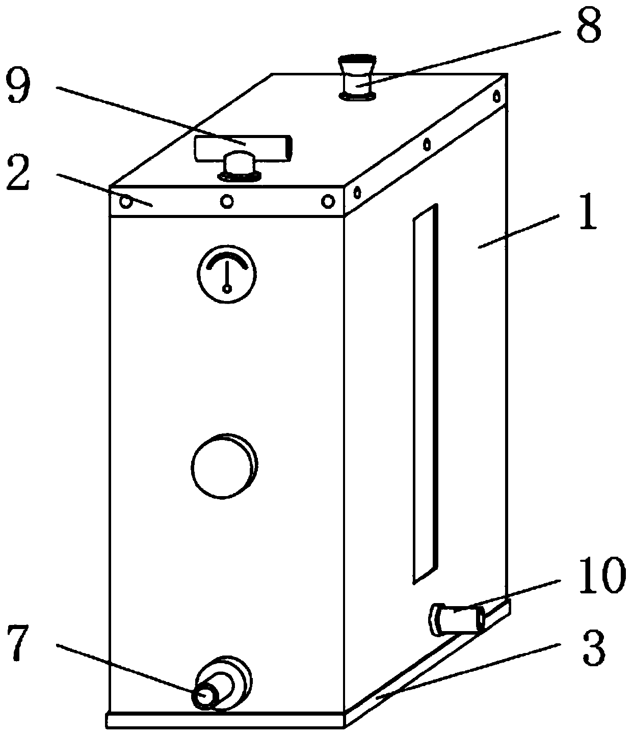
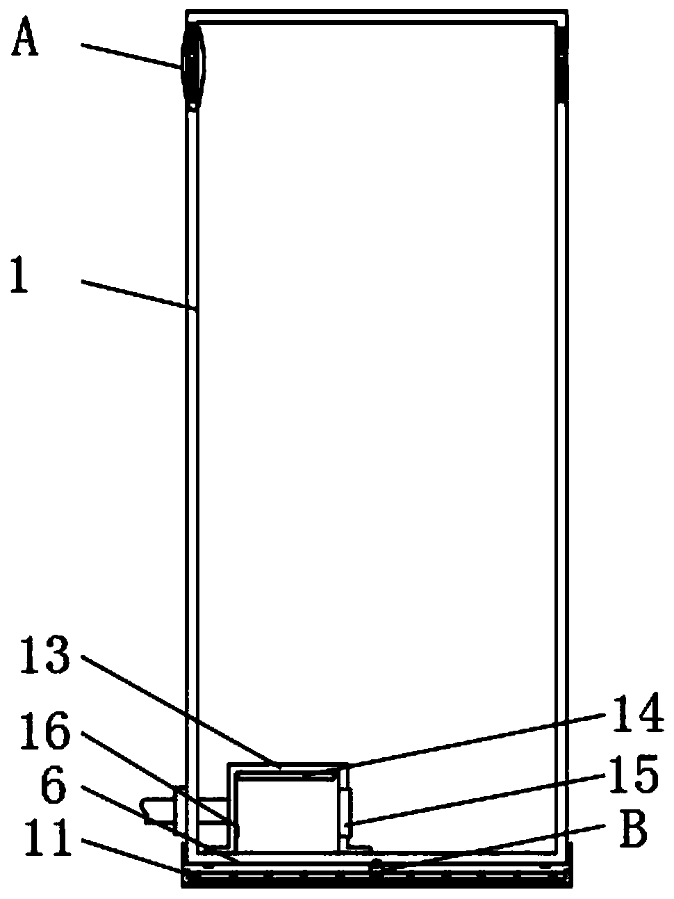
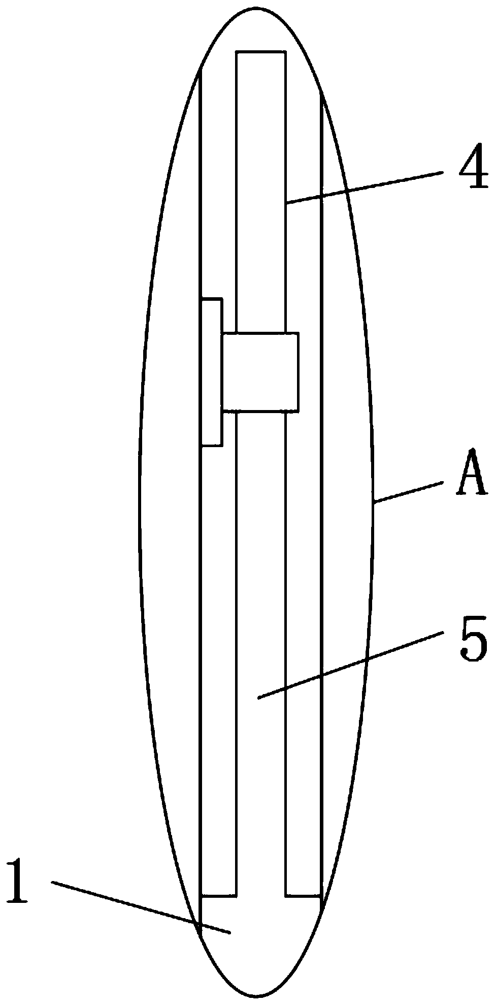
[0036] A pressurized tank...


PUM


Abstract

The invention discloses a pressure-bearing water tank structure and a machining process. The pressure-bearing water tank structure comprises a water tank main body, a water tank upper cover and a water tank base. The outer surface of the lower end of the water tank upper cover is provided with a clamping groove, a clamping strip is integrally formed in the outer surface of the upper end of the water tank main body, the clamping strip is positioned in the clamping groove, and the clamping strip and the clamping groove are fixedly connected through bolts. According to the pressure-bearing watertank structure and the machining process, the water tank upper cover and the water tank main body can be separated, internal devices of the pressure-bearing water tank can be conveniently repaired bypeople, the water tank upper cover and the water tank main body can be repeatedly utilized, the material utilization rate is higher, the vibration of the pressure-bearing water tank can be reduced, the connection effect of a pipeline on the vibration pressure-bearing water tank is reduced, the service life of the pipeline on the pressure-bearing water tank is prolonged, and finally the temperatureof cooling liquid can be increased to the optimal performance temperature, so that the use effect of the whole liquid cooling device is improved, and a better use prospect is brought.

Description

technical field [0001] The invention relates to the field of air conditioning, in particular to a pressurized water tank structure and processing technology. Background technique [0002] With the development of society and the continuous improvement of people's living standards, various equipment continue to appear, and the equipment is becoming more and more sophisticated, and the volume is getting smaller and smaller, and the sealing performance is getting higher and higher. In order to maintain the stability of the equipment People have invented a liquid cooling device that can maintain the working temperature of the equipment, and an important part of the liquid cooling device is its pressurized water tank structure. With the rapid development of science and technology, people's requirements for the pressurized water tank of the liquid cooling device are also increasing. The continuous increase has caused the existing pressurized water tanks to fail to meet people's use...

Claims


Application Information

Patent Timeline
IPC IPC(8): F24F5/00
CPCF24F5/0007
Inventor 刘余根胡明贵吴冬平
Owner 合肥通用制冷设备有限公司
Why Eureka
Try Eureka