Antenna control system and method and mobile terminal

An antenna control and antenna technology, applied in antennas, transmission systems, antenna arrays, etc., can solve problems such as poor adaptability and insensitive switching of left and right antennas, and achieve the effect of balancing the functions of left and right heads and hands

Active Publication Date: 2017-07-04
VIVO MOBILE COMM CO LTD
View PDF9 Cites 8 Cited by
  • Summary
  • Abstract
  • Description
  • Claims
  • Application Information

AI Technical Summary

Problems solved by technology

[0004] Embodiments of the present invention provide an antenna control system, method, and mobile terminal to solve or partially solve the above-mentioned problem of insensitive switching between left and right antennas or poor adaptability when improving left and right head-hand performance of mobile terminal antennas

Method used


Image

  • Antenna control system and method and mobile terminal
  • Antenna control system and method and mobile terminal
  • Antenna control system and method and mobile terminal

Examples


Embodiment 1

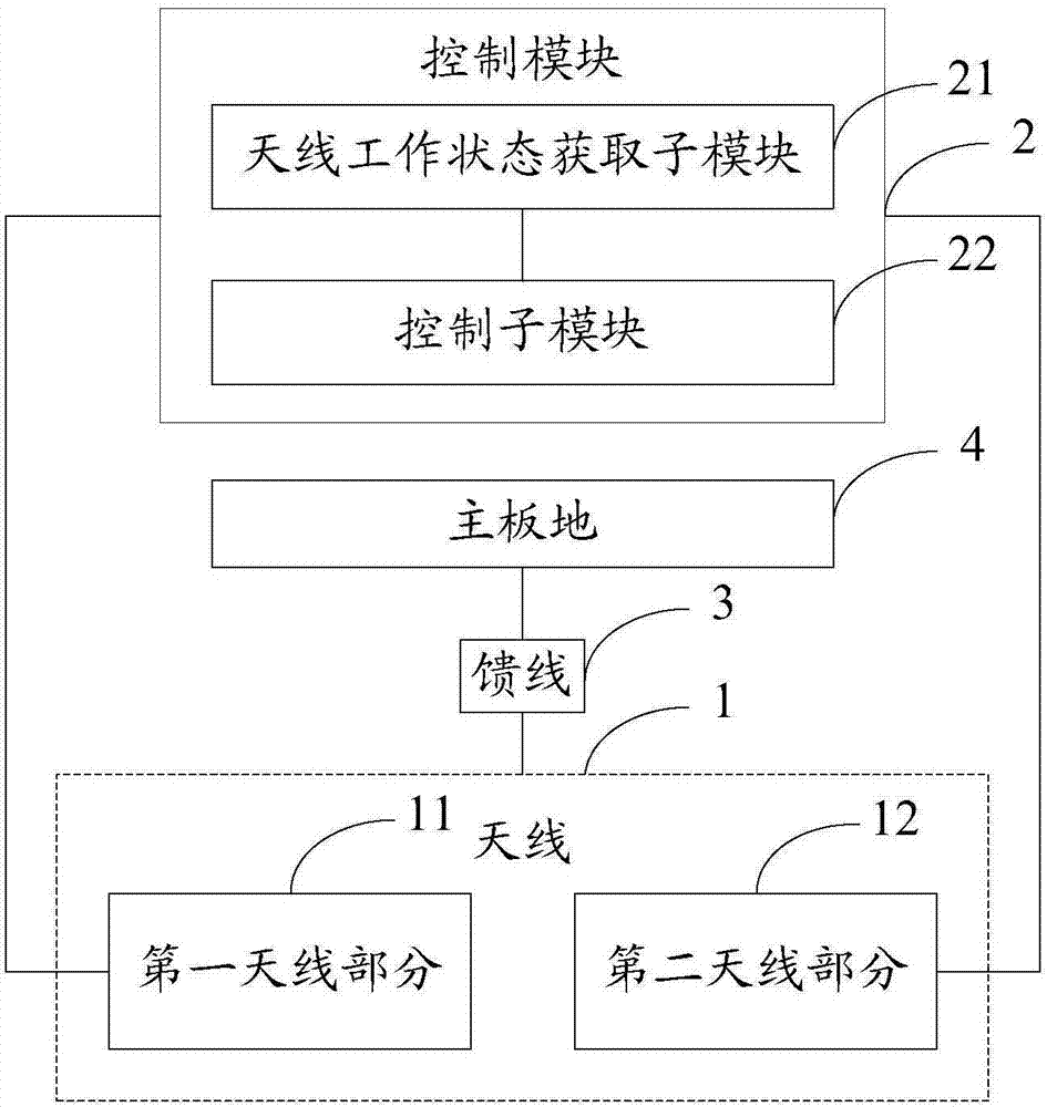
[0028] Reference figure 2 As shown, a schematic structural diagram of an antenna control system according to an embodiment of the present invention is shown, which may specifically include: an antenna 1 and a control module 2;

[0029] The antenna 1 may specifically include: a first antenna portion 11 and a second antenna portion 12 that are symmetrically distributed; the first antenna portion 11 and the second antenna portion 12 respectively have multiple operating states and correspond to multiple operating resonance frequencies;

[0030] The aforementioned control module 2 may specifically include:

[0031] The antenna working state acquiring sub-module 21 is used to acquire the first working state of the first antenna part 11;

[0032] The control sub-module 22 is used to adjust the second working state of the second antenna part 12 according to the first working state, so that the working resonance frequency of the first antenna part 11 and the working resonance frequency of the ...

Embodiment 2

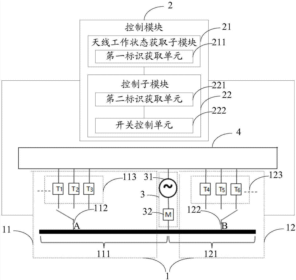
[0042] Reference image 3 As shown, a schematic structural diagram of an antenna control system according to an embodiment of the present invention is shown, which may specifically include: an antenna 1 and a control module 2;

[0043] The antenna 1 may specifically include: a first antenna portion 11 and a second antenna portion 12 that are symmetrically distributed; the first antenna portion 11 and the second antenna portion 12 respectively have multiple operating states and correspond to multiple operating resonance frequencies;

[0044] The first antenna part 11 is composed of a first antenna 111, a first switch 112, and a first multiple tuning circuit 113 in series; the second antenna part 12 is composed of a second antenna 121, a second switch 122, and a second multiple tuning circuit. 123 is composed in series; the first multiple tuning circuit 113 and the second multiple tuning circuit 123 are respectively composed of multiple tuning branches in parallel;

[0045] There is a ...

Embodiment 3

[0080] Reference Figure 5 As shown, a step flow chart of an antenna control method according to an embodiment of the present invention is shown. The antenna may specifically include: a first antenna part and a second antenna part that are symmetrically distributed; the first antenna part and the second antenna The parts respectively have multiple working states and correspond to multiple working resonance frequencies; the above method may specifically include steps 501-502:

[0081] Step 501: Obtain the first working state of the above-mentioned first antenna part.

[0082] Step 502: Adjust the second working state of the second antenna part according to the first working state, so that the difference between the working resonance frequency of the first antenna part and the working resonance frequency of the second antenna part is less than a set threshold.

[0083] For the description of the above steps 501-502, please refer to the description in the first embodiment, which will no...


PUM


Abstract

The embodiment of the invention relates to the field of communication, in particular relates to an antenna control system and method and a mobile terminal. The system comprises an antenna and a control module, wherein the antenna comprises a first antenna part and a second antenna part which are symmetrically distributed, the first antenna part and the second antenna part respectively has various working states corresponding to various working resonant frequencies, the control module comprises an antenna working state acquisition sub-module and a control sub-module, the antenna working state acquisition sub-module is used for acquiring a first working state of the first antenna part, the control sub-module is used for adjusting a second working state of the second antenna part according to the first working state, so that the difference value between the working resonant frequency of the first antenna part and the working resonant frequency of the second antenna part is smaller than a set threshold value, antenna energy is more uniformly distributed at two sides of the antenna, left/right antenna switching is not needed to be performed according to an actual application scene of the mobile terminal, and the technical effect of balancing a left head and hand function and a right head and hand function of the antenna is achieved.

Description

Technical field [0001] The present invention relates to the field of communications, in particular to an antenna control system, method and mobile terminal. Background technique [0002] Reference figure 1 As shown, among the antenna technologies currently used in mobile terminals, common ones include monopole, inverted F-shaped antenna (IFA), loop antenna (LOOP), etc. The antenna feed is often placed in The corner on the left or right side of the mobile terminal is the single resonant arm antenna design. However, because the single resonant arm antenna resonates on a single branch on the left or right side, the antenna energy is too concentrated on the branch, which makes the electric field strength difference between the left and right sides of the mobile terminal very large, and the antenna branch that is biased to the head and hand side absorbs The loss will increase significantly, leading to a big difference in the performance of the head or hand. [0003] In the related art...

Claims


Application Information

Patent Timeline
Patent Type & Authority Applications(China)
IPC IPC(8): H01Q3/00H01Q5/10H01Q21/00H04M1/725H04M1/02H04M1/72403H04M1/72448
CPCH01Q3/00H01Q5/10H01Q21/00H04M1/0202H04M1/026H04M1/72448H04M1/72403H01Q1/243H01Q9/0442H04B1/40H04B1/005H01Q5/328H01Q1/523
Inventor 李日辉
Owner VIVO MOBILE COMM CO LTD
Why Eureka
Try Eureka