Method and device for measuring and calibrating microphone

A microphone and standard technology, applied in the direction of electrical components, etc., can solve the problems of high calibration cost, the frequency of calibration points cannot be freely selected, and low calibration efficiency, so as to save calibration and measurement costs, achieve portability, and simple operation Effect

Inactive Publication Date: 2017-07-04
BEIJING AERONAUTIC SCI & TECH RES INST OF COMAC +1
View PDF4 Cites 21 Cited by
  • Summary
  • Abstract
  • Description
  • Claims
  • Application Information

AI Technical Summary

Problems solved by technology

[0005] 1. The sensitivity calibration method can only calibrate a single microphone, and cannot calibrate multiple microphones at the same time. In addition, there are few frequency points for calibration, the frequency of the calibration point cannot be freely selected, the calibration efficiency is low, and the calibration frequency characteristics are not good. comprehensive and other issues;
[0006] 2. Sensitivity calibration or phase calibration can only be performed separately, but these two characteristics cannot be calibrated at the same time, resulting in low calibration efficiency. When the number of microphones to be tested is large, it will take a lot of time;
[0007] 3. Since two different methods are used for sensitivity calibration and phase calibration, two sets of calibration equipment need to be purchased, resulting in high calibration costs;
In practical applications, it is necessary to build a special anechoic chamber to simulate the free sound field. The construction cost of the anechoic chamber is very expensive, and the phase calibration measurement method is complicated.
At the same time, the anechoic chamber cannot be moved arbitrarily. When external field measurements are required, the requirements for on-site calibration cannot be met, and the phase calibration of the microphone cannot be performed in time.

Method used


Image

  • Method and device for measuring and calibrating microphone
  • Method and device for measuring and calibrating microphone

Examples


Embodiment Construction

[0028] In order to make the object, technical solution and advantages of the present invention clearer, the present invention will be further described in detail below in combination with specific embodiments and with reference to the accompanying drawings. It should be understood that these descriptions are exemplary only, and are not intended to limit the scope of the present invention. Also, in the following description, descriptions of well-known structures and techniques are omitted to avoid unnecessarily obscuring the concept of the present invention.

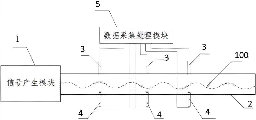
[0029] see figure 1 , figure 1 It is a schematic diagram of the module relationship of the device for measuring microphone characteristics provided by the first embodiment of the present invention.

[0030] Such as figure 1 As shown, in the embodiment of the present invention, the device for measuring the characteristics of the microphone includes: a signal generation module 1 , a sound tube 2 , a standard microphone 3...


PUM


Abstract

The invention discloses a device for measuring the characteristics of a microphone. The device for measuring the characteristics of the microphone comprises a signal generating module, a sound transmission tube, a standard microphone and a data acquisition and processing module; wherein the signal generating module generates a corresponding acoustical signal according to the electrical signal with a particular frequency; the sound transmission tube transmits the acoustical signal to the other end of the sound transmission tube from the end which the source located in with the form of plane waves with the particular frequency; the standard microphone and the microphone to be measured are respectively inserted into the tube wall of the the sound transmission tube, used for collecting the acoustical signal in the sound transmission tube and converting the acoustical signal to an electrical signal and sending; and the data acquisition and processing module obtains the phase difference between the microphone to be measured and the standard microphone according to the phase measured by the standard microphone and the phase measured by the microphone to be measured, obtains the amplitude of the standard microphone based on the electrical signal sent by the standard microphone, and obtains the sensitivity of the microphone to be measured based on the amplitude and the electrical signal measured by the microphone to be measured. According to the invention, the measuring and calibrating of multiple microphones is realized at the same time, and the phase and sensitivity of the microphone are measured and calibrated at the same time, therefore, the cost is saved, and the efficiency of measurement and calibration is improved.

Description

technical field [0001] The invention relates to the field of sound wave processing, in particular to a method and device for measuring and calibrating a microphone. Background technique [0002] When microphones are used in the fields of sound source identification and positioning, noise control, etc., multiple microphones are required to collect sound at the same time. In order to ensure the accuracy of the collected data source, the characteristics of each microphone need to be determined. Since the characteristics of the microphone will change with time, temperature, humidity and other environments, it is necessary to calibrate the characteristics of the microphone before using the microphone to reduce data errors caused by changes in the characteristics of the microphone. [0003] Existing calibrations for microphone characteristics include: sensitivity calibration and phase calibration. Among them, the sensitivity calibration method is: use a piston generator to genera...

Claims


Application Information

Patent Timeline
Patent Type & Authority Applications(China)
IPC IPC(8): H04R29/00
CPCH04R29/004
Inventor 张颖哲林大楷陈超陈哲
Owner BEIJING AERONAUTIC SCI & TECH RES INST OF COMAC
Why Eureka
Try Eureka