Active output driving circuit of input and output module and implementation method of active output driving circuit

A technology of input and output modules and output drive circuits, which is applied in the direction of emergency protection circuit devices, measuring electricity, electrical components, etc., can solve problems such as time-consuming and labor-consuming, excessive wiring, damage to circuit components and peripheral equipment, and achieve circuit design. Simple and reasonable, convenient operation and low price

Active Publication Date: 2017-07-07
SICHUAN SAIKE SECURITY TECH CO LTD
View PDF4 Cites 4 Cited by
  • Summary
  • Abstract
  • Description
  • Claims
  • Application Information

AI Technical Summary

Problems solved by technology

Although the active output drive circuit realized by the existing design method can meet the national standard, there are many components in the circuit. When drawing the circuit board, not only the wiring is too much and the wiring method is relatively complicated, but also some key components The price is expensive, so it is not only time-consuming and labor-intensive, but also the design cost is relatively high
[0004] Based on this, although the document with the patent application number 201510247152.6 discloses the power supply method of the two-wire communication bus, which solves the problem that the input and output modules need external power supply and reduces the cost in the application process, but it still needs to be powered by the relay. Turn on and off peripheral devices
Moreover, when the peripheral equipment fails (such as short circuit), the existing technology cannot effectively protect it, resulting in easy damage to circuit components and peripheral equipment, and may even cause safety accidents in severe cases

Method used


Image

  • Active output driving circuit of input and output module and implementation method of active output driving circuit
  • Active output driving circuit of input and output module and implementation method of active output driving circuit

Examples


Embodiment Construction

[0029] The present invention will be further described below with reference to the accompanying drawings and embodiments, and the mode of the present invention includes but not limited to the following embodiments.

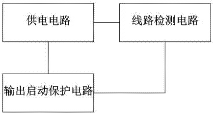
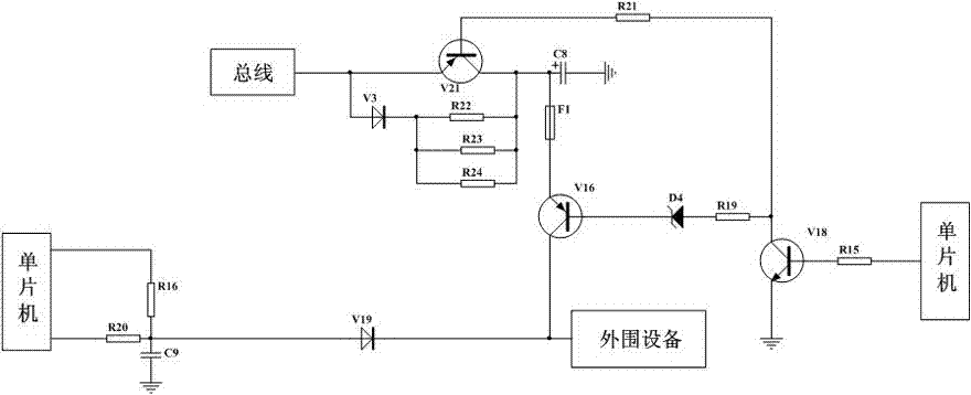
[0030] like figure 1 and figure 2 As shown, the present invention provides a new type of output driving circuit, which is mainly composed of three parts: power supply circuit, output start-up protection circuit and line detection circuit. Active output control of the device. The power supply circuit, the output startup protection circuit and the line detection circuit are introduced in detail below.

[0031] The power supply circuit is composed of a diode V3, a transistor V21, a capacitor C8 and three resistors (R22, R23, R24). The anode of the diode V3 is connected to the bus, and the three resistors R22, R23, and R24 are connected in parallel. One end of each is connected to the cathode of the diode V3, and the other ends of the three resistors R22, R23, R24...


PUM


Abstract

The invention discloses an active output driving circuit of an input and output module. The active output driving circuit comprises a supply circuit, an output starting protection circuit and a line detection circuit. The supply circuit comprises a diode V3, a triode V21 and a capacitor C8. The output starting protection circuit comprises a triode V16, a voltage stabilizing diode D4 and a triode V18. The line detection circuit comprises a resistor R16, a resistor R20, a capacitor C9 and a diode V19. A bus directly supplies power to the active output driving circuit for operation, no relay needs to be adopted, in addition, peripheral equipment can be subjected to effective voltage reduction protection when breaking down, and normal communication of the bus is guaranteed. Therefore, the active output driving circuit is suitable for application and popularization.

Description

technical field [0001] The invention relates to the technical field of fire protection, in particular to an active output drive circuit of an input and output module and a realization method thereof. Background technique [0002] The input and output module is also called the control module, which is an important part of the fire alarm linkage system. When there is a control requirement, it can output a signal, or provide a switch signal to make the controlled device act, and at the same time receive the feedback signal of the device , to report to the host. [0003] In the current active output drive mode of the input and output modules, the circuit part usually needs to design a 24V power supply circuit for power supply, and at the same time, it needs to be connected to the peripheral equipment through a relay, and other components such as optocouplers are used to form a line detection circuit to monitor the peripheral equipment. to test. Although the active output drive...

Claims


Application Information

Patent Timeline
Patent Type & Authority Applications(China)
IPC IPC(8): A62C37/50G08B17/06
CPCA62C37/50G01R31/50H02H7/20
Inventor 不公告发明人
Owner SICHUAN SAIKE SECURITY TECH CO LTD
Why Eureka
Try Eureka