Automatic sorting machine

An automatic sorting and rack technology, applied in sorting and other directions, can solve the problems of small black spots on capsules and turntable wear, low capsule linear speed, and affecting product quality, so as to control capsule waste, reduce small black residue, The effect of improving the quality and efficiency of site clearance

Pending Publication Date: 2017-07-07
青岛益青生物科技股份有限公司
View PDF6 Cites 0 Cited by
  • Summary
  • Abstract
  • Description
  • Claims
  • Application Information

AI Technical Summary

Problems solved by technology

The automatic sorting machine includes a circular feeding tray, because the drive shaft driving the circular feeding tray is located directly below the circular feeding tray, and there is a shaft on it for separating the circular feeding tray and the drive shaft header cover ( figure 1 In A), the concentric turntable and the shaft head cover rotate at the same angular speed with the center of the circle as the center. When the capsules fall into the circular feeding tray from the feeding port, some capsules will bounce down to the shaft head cover, and the shaft head The linear speed of the capsules on the cover is very low, and it is difficult to roll to the edge of the circular feeding tray and enter the chain, causing the capsules to remain in the circular feeding tray for a long time and contact with the air, resulting in water loss
In order to prevent this from happening, a partition is currently set up on the circular feeding tray to distribute the capsules. Because the bottom of the partition uses a silicone soft leather for distribution, the capsules are easily stuck between the silicone soft leather and the circular feeding tray. , long-term wear and tear of the capsule and the turntable will produce small black spots, and the small black spots will stick to the capsules and affect product quality

Method used


Image

  • Automatic sorting machine
  • Automatic sorting machine

Examples


Embodiment Construction

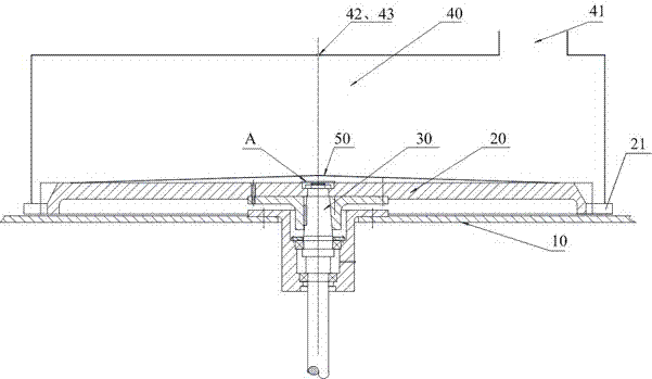
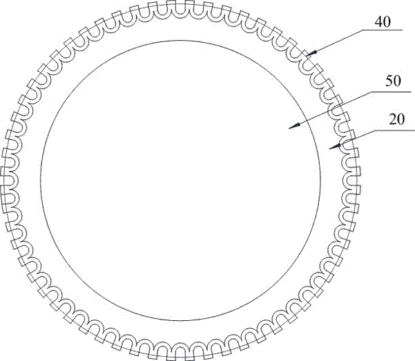
[0021] In order to make the objectives, technical solutions and advantages of the present invention clearer, the present invention will be described in further detail below with reference to the accompanying drawings and embodiments. It should be understood that the embodiments described herein are only used to explain the present invention, but not to limit the present invention.

[0022] In the following description, numerous specific details are set forth in order to provide a more thorough understanding of the present invention. It will be apparent, however, to one skilled in the art that the present invention may be practiced without one or more of these details. In other instances, some technical features known in the art have not been described in order to avoid obscuring the present invention.

[0023] For a thorough understanding of the present invention, detailed structures will be presented in the following description. Obviously, the practice of the present inven...


PUM


Abstract

The invention provides an automatic sorting machine. The automatic sorting machine comprises a rack, a round discharging disk, a transmission shaft and a material storing bin which is located above the round discharging disk; a feeding port is formed in one side of the top of the material storing bin; the transmission shaft is connected to the rack; the upper end of the transmission shaft is connected with the round discharging disk, and the round discharging disk is driven to rotate; a plurality of square teeth are arranged on the circumferential circle of the round discharging disk; a conical material distributing cover with a downward opening is fixedly arranged in the middle of the top face of the round discharging disk; and the diameter of the opening of the conical material distributing cover is 0.6-0.8 of the diameter of the round discharging disk. The conical material distributing cover is arranged to make capsules roll to the circumference of the round discharging disk by themselves, gas blowing is added over the round discharging disk to assist in capsule material distributing, and in this way, it is avoided that the capsules stay in the round discharging disk for a long time, and consequently the water loss is caused; and meanwhile, site clearing is convenient, and therefore the capsule waste amount is controlled, the problems of capsule residues and small black slag are reduced, the site clearing quality and efficiency of the automatic sorting machine is substantially improved, and the product quality is guaranteed.

Description

technical field [0001] The invention belongs to the technical field of capsule production, in particular to an automatic sorting machine, and mainly relates to an anti-retention device for capsules on a circular feeding tray of the automatic sorting machine. Background technique [0002] In the capsule production line, an automatic sorting machine is used to remove unqualified capsules. The automatic sorting machine includes a circular unloading tray, because the drive shaft driving the circular unloading tray is located just below the circular unloading tray, and there is a shaft on it for separating the circular unloading tray and the drive shaft. head cover ( figure 1 A) in the middle, the concentric turntable and the shaft head cover rotate together with the center of the circle at the same angular speed. When the capsules fall into the circular unloading tray from the feeding port, some capsules will bounce to the shaft head cover, and the shaft head The linear speed ...

Claims


Application Information

Patent Timeline
Patent Type & Authority Applications(China)
IPC IPC(8): B07C5/342B07C5/36
CPCB07C5/342B07C5/365
Inventor 刘东光郝刚初亮
Owner 青岛益青生物科技股份有限公司
Why Eureka
Try Eureka