Forging die capable of achieving automatic discharging

An automatic unloading and moving mold technology, which is applied in the direction of manufacturing tools, forging/pressing/hammer devices, forging/pressing/hammering machinery, etc., can solve the problem that the forging mold cannot be unloaded automatically, so as to improve the demoulding efficiency and Forging efficiency, simple structure, and the effect of reducing labor intensity

Active Publication Date: 2017-07-07
四川瑞丰锻造有限公司
View PDF6 Cites 5 Cited by
  • Summary
  • Abstract
  • Description
  • Claims
  • Application Information

AI Technical Summary

Problems solved by technology

[0004] The object of the present invention is to provide a forging die capable of automatic discharge in view of the above-mentioned problem that the existing forging die cannot be automatically unloaded

Method used


Image

  • Forging die capable of achieving automatic discharging
  • Forging die capable of achieving automatic discharging
  • Forging die capable of achieving automatic discharging

Examples


Embodiment 1

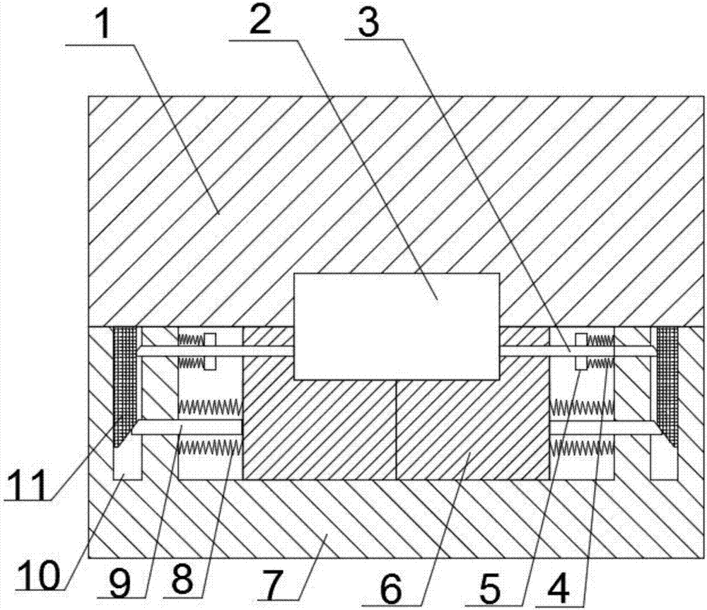
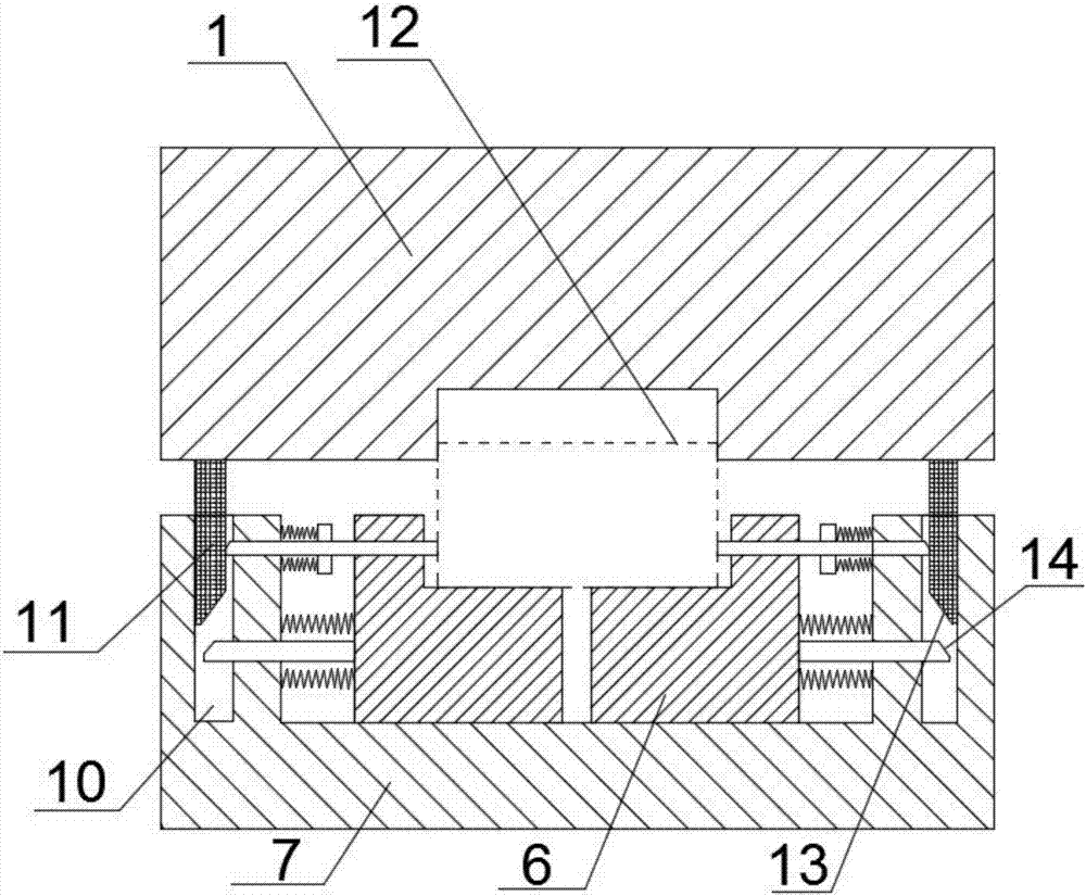
[0021] A forging mold capable of automatic unloading, comprising a movable mold 7 and a fixed mold 1, the upper end of the movable mold 7 and the lower end of the fixed mold 1 are provided with relative concave molds, and the concave mold on the movable mold 7 is There are two moving blocks 6, the moving blocks 6 are L-shaped and oppositely arranged, and form a cavity 2 matching the shape of the forging with the fixed die 1; Rod 11, the two ends of the movable mold 7 are provided with a groove 10 cooperating with the pressure rod 11, and the free end of the pressure rod 11 is provided with a first slope 13; the two ends of the movable mold 7 are provided with a first unloading mechanism And the second unloading mechanism, the first unloading mechanism includes a horizontal push rod 9 fixedly connected with the moving block 6 and the first elastic member 8 connecting the moving block 6 and the inner wall of the die, and the free end of the push rod 9 stretches into the groove 1...

Embodiment 2

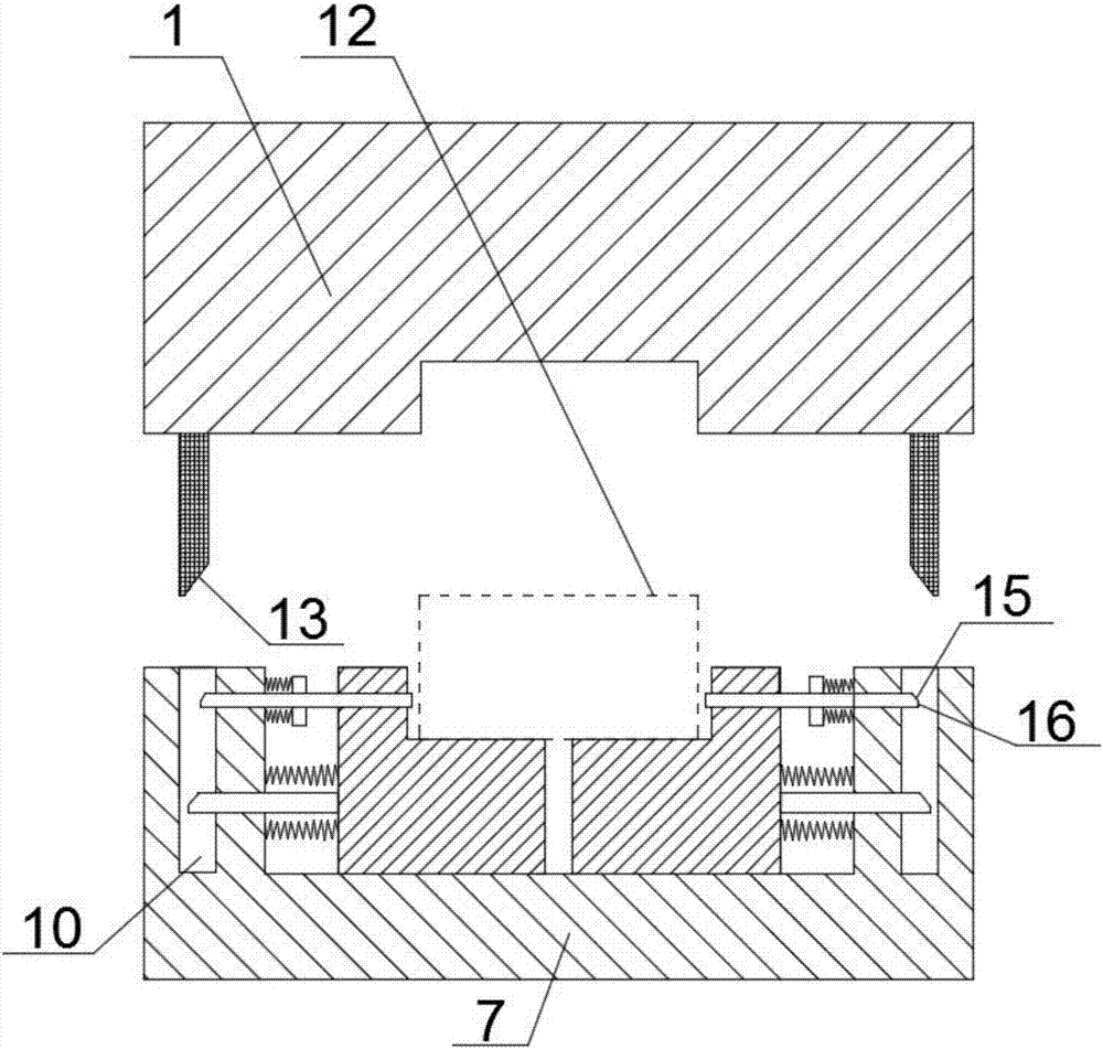
[0024] Based on Embodiment 1, a stop surface 16 is provided at the lower end of the third slope 15 , and the stop surface 16 is in contact with the outer wall of the pressing rod 11 . By setting the stop surface 16 , it is beneficial to keep the fixing rod 3 stable during the movement of the pressing rod 11 relative to the groove 10 .

Embodiment 3

[0026] Based on Embodiment 1, there are gaps between the push rod 9 and the inner wall of the groove 10 and between the fixed rod 3 and the inner wall of the groove 10 for the front end of the pressure rod 11 to pass through, which can effectively prevent the push rod 9 and the fixed rod 3 from reaching the groove 10. The contact of the inner walls affects the cooperation of the first slope 13 , the second slope 14 and the third slope 15 .


PUM


Abstract

A forging die capable of achieving automatic discharging comprises a moving die and a fixed die, wherein opposite concave dies are arranged at the upper end of the moving die and the lower end of the fixed die separately, and two moving blocks are arranged on the concave die on the moving die; the two ends of the fixed die extend downwards, forming pressing rods; grooves matched with the pressing rods are formed in the two ends of the moving die, and a first oblique plane is arranged at the free end of each pressing rod; two first discharging mechanisms and two second discharging mechanisms are arranged at the two ends of the moving die separately; each first discharging mechanism comprises a horizontal pushing rod and a first elastic part, the free end of each pushing rod stretches into the corresponding groove, and a second oblique plane matched with the corresponding first oblique plane is arranged at the free end of each pushing rod; each second discharging mechanism comprises a fixed rod and a connecting plate, one end of each fixed rod stretches into the corresponding groove, a third oblique plane matched with the corresponding first oblique plane is arranged at one end of each fixed rod, the other end of each fixed rod passes through the corresponding moving block and forms an end of a cavity with the corresponding moving block and the fixed die, and each connecting plate is connected with the inner wall of the concave die through a second elastic part. The forging die can automatically discharge forged parts during die release, labor intensity of workers is relieved, and die release efficiency and forging efficiency are improved.

Description

technical field [0001] The invention belongs to the technical field of forging dies, in particular to an automatic unloading forging die. Background technique [0002] The forging mold refers to heating the metal first to become a liquid or softened state, then putting it into the mold, and forming it at one time by closing the upper and lower molds of the mold. The advantage of forging and casting is that casting is to pour heated molten metal directly into the mold, while die forging also needs to be closed by the upper and lower molds. The closing of the upper and lower molds makes the product subject to extrusion force during the molding process, and its structure and mechanical properties have been enhanced. [0003] After the forging die in the prior art is demoulded, it is usually necessary to manually remove the forging from the die, which increases the labor intensity of the workers, and if the forging cannot be removed from the die in time, it will also affect the...

Claims


Application Information

Patent Timeline
Patent Type & Authority Applications(China)
IPC IPC(8): B21J13/02
CPCB21J13/025
Inventor 黄韬
Owner 四川瑞丰锻造有限公司
Why Eureka
Try Eureka