PCB separating and conveying frame grabbing mechanism

A technology of grabbing mechanism and conveying rack, which is applied in the direction of conveyors, conveyor objects, transportation and packaging, etc. It can solve the problems of manual classification troubles, affecting the yield of finished products, and low efficiency, so as to improve the continuity of processing and high degree of automation , The effect of facilitating subsequent processing

Inactive Publication Date: 2017-07-07
徐州对河建材有限公司
View PDF4 Cites 2 Cited by
  • Summary
  • Abstract
  • Description
  • Claims
  • Application Information

AI Technical Summary

Problems solved by technology

[0004] The existing PCB sub-boards generally use manual sub-boards, which have poor effect and low efficiency, and manual sub-boards are easy to damage the board and affect the yield, so mechanical sub-boards are now used;
[0005] However, in the existing mechanical sub-boards, the slit PCB sub-boards are generally placed on the placement board, and then manually transport the placement board to the designated position, which is very troublesome and inefficient
[0006] Moreover, PCB sub-boards of different specifications generally need to be placed on placement boards of different sizes, which makes manual classification troublesome.

Method used


Image

  • PCB separating and conveying frame grabbing mechanism
  • PCB separating and conveying frame grabbing mechanism

Examples


Embodiment Construction

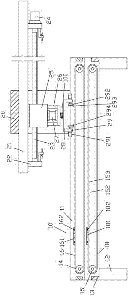
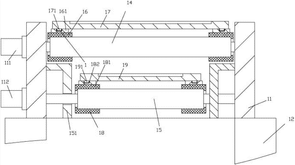
[0026] Examples, see e.g. Figure 1 to Figure 2 As shown, a grabbing mechanism for a PCB sub-board conveying frame includes a frame body 10, and the frame body 10 includes two side plates 11, the bottom of the side plates 11 is fixed with support legs 12, and a plurality of transverse beams 13 are located between two The two ends of the side plate 11 and the two ends of the transverse beam 13 are fixed on the inner side walls of the two side plates 11;

[0027] The top between the two side plates 11 is provided with two upper conveyor belts 16, the bottom is provided with two lower conveyor belts 18, the upper placement plate 17 is on the two upper conveyor belts 16, and the lower placement plate 19 is on the two upper conveyor belts 16. On the lower conveyor belt 18;

[0028] The upper right end upper part of described two side boards 11 is fixed with upper grab connection frame 20, and the bottom surface of the top plate of last grab connection frame 20 is fixed with delive...


PUM


Abstract

The invention discloses a PCB separating and conveying frame grabbing mechanism which comprises a frame body. The frame body comprises two side boards. Supporting legs are fixed to the bottoms of the side boards. Multiple transverse beams are located at the two ends of the two side boards. The two ends of each transverse beam are fixed to the inner side walls of the two side boards. Two upper conveying belts are arranged on the upper portion of the position between the two side boards, and two lower conveying belts are arranged on the lower portion of the position between the two side boards. An upper placement board is located on the two upper conveying belts, and a lower placement board is located on the two lower conveying belts. An upper grabbing connecting frame is fixed to the upper portions of the right ends of the two side boards, a conveying board is fixed to the bottom face of a top board of the upper grabbing connecting frame, and conveying supporting boards are fixed to the bottom faces of the two ends of the conveying board. The PCB separating and conveying frame grabbing mechanism is provided with the upper placement board and the lower placement board, and therefore separated PCBs of different specifications can be contained, then automatically conveyed and grabbed and carried to subsequent machining stations; subsequent machining is facilitated; manual carrying is not needed; machining continuity is improved; and the automation degree is high.

Description

[0001] Technical field: [0002] The invention relates to the technical field of circuit board manufacturing and processing, and more specifically relates to a grasping mechanism of a PCB sub-board conveying frame. [0003] Background technique: [0004] The existing PCB sub-boards generally use manual sub-boards, which have poor effect and low efficiency, and manual sub-boards are easy to damage the board and affect the yield, so mechanical sub-boards are now used; [0005] However, in the existing mechanical sub-boards, the cut PCB sub-boards are generally placed on the placement board, and then the placement board is manually transported to the designated position, which is very troublesome and inefficient. [0006] Moreover, PCB sub-boards of different specifications generally need to be placed on placement boards of different sizes, which makes manual classification troublesome. [0007] Invention content: [0008] The purpose of the present invention is to overcome the ...

Claims


Application Information

Patent Timeline
Patent Type & Authority Applications(China)
IPC IPC(8): B65G47/90
CPCB65G47/901B65G2201/022
Inventor 王松
Owner 徐州对河建材有限公司
Why Eureka
Try Eureka