Variable-damping vibration damper for washing machine and washing machine

A vibration damping device and variable damping technology, applied in the field of washing machines, can solve problems such as abnormal vibration noise, loss of vibration damping effect, large vibration of washing machines, etc., and achieve the effect of improving vibration noise level, improving vibration damping performance, and good dehydration stability

Inactive Publication Date: 2017-07-07
HEFEI HAIER WASHING MACHINE
View PDF6 Cites 8 Cited by
  • Summary
  • Abstract
  • Description
  • Claims
  • Application Information

AI Technical Summary

Problems solved by technology

[0005] However, after the spring is completely compressed, the vibration-damping effect is lost. Therefore, when the washing machine is washed and dehydrated, the suspension rod cannot play a good vibration-damping effect, resulting in a large vibration and a large moving distance of the washing machine.
In the dehydration transient stage, the internal system vibrates greatly, and the boom device is required to provide a relatively large damping force to suppress the internal system vibration; in the dehydration steady state stage, the internal system vibration is small, and the boom device is required to provide a relatively small damping force. The above-mentioned sus

Method used


Image

  • Variable-damping vibration damper for washing machine and washing machine
  • Variable-damping vibration damper for washing machine and washing machine
  • Variable-damping vibration damper for washing machine and washing machine

Examples


Embodiment 1

[0037] Such as Figure 4As shown, the upper surface of the tray 81 described in this embodiment is provided with an annular protrusion 84 along the outer periphery of the boom installation hole 83. The annular protrusion 84 is gradually lowered from the inside to the outside. The missing shape structure, the boom mounting hole 83 runs through the center, and the contact surface between the lower part of the upper support 2 and the upper surface of the tray 81 is a concave pressing surface matched with the ring-shaped protrusion 84 (refer to Figure 6 ), the annular protrusion 84 is the first variable damping structure 9 on the tray 81 .

[0038] Further, the first variable damping structure 9 is two concentric ring-shaped protrusions 84 on the inner and outer surfaces of the tray 81 .

Embodiment 2

[0040] Such as Figure 5 As shown, at least one compression bead 85 is provided on the peripheral wall of the support sleeve 82 described in this embodiment. The rib 85 is the second variable damping structure 10 on the support sleeve 82 . The upwardly extending end of the compression rib 85 is smoothly connected to the lower surface of the tray 81 .

[0041] Preferably, there are 4-6 compression ribs 85 uniformly distributed along the circumferential direction of the support sleeve 82 .

Embodiment 3

[0043] The difference between this embodiment and the second embodiment is that the outer diameter of the support sleeve gradually increases from bottom to top, and the upper end of the support sleeve and the lower surface of the tray smoothly transition (not shown in the figure).


PUM


Abstract

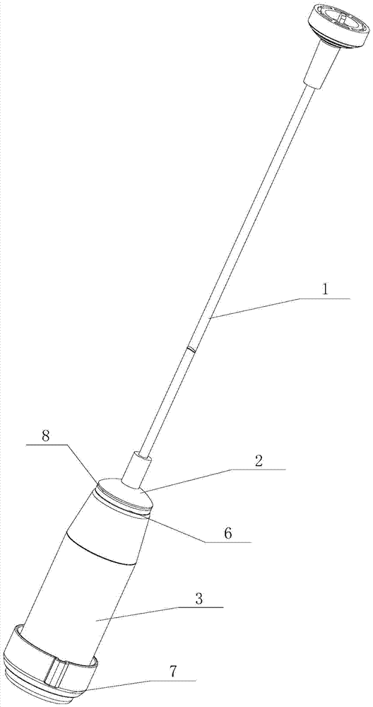
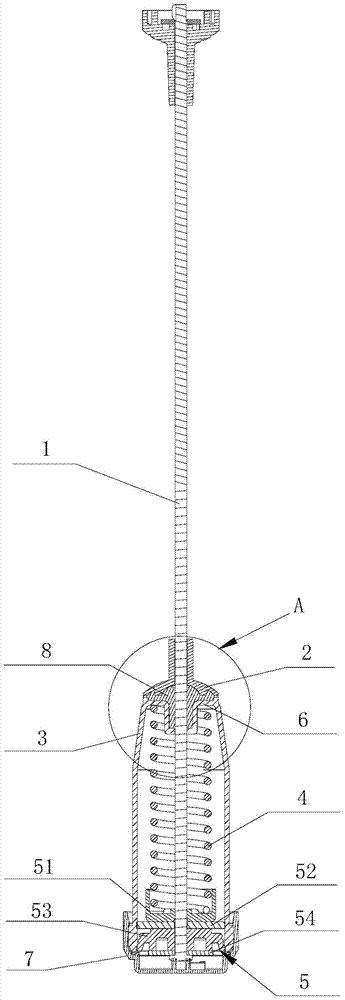
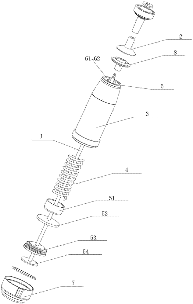
The invention discloses a variable-damping vibration damper for a washing machine and the washing machine. The variable-damping vibration damper comprises a hosting rod, an upper support, a sleeve pipe and a pressure buffer mechanism arranged in the sleeve pipe. The upper end of the sleeve pipe is provided with a bracket and the lower end of the sleeve pipe is provided with a bottom cover. The hanging rod penetrates through the upper support and the bracket extends into the sleeve pipe to be connected with the pressure buffer mechanism. A damping sleeve is arranged between the upper support and the bracket. The hanging rod penetrates through the damping sleeve. The damping sleeve provides variable damping force to the hoisting rod. The damping sleeve is extruded by the upper support and the bracket and is deformed. By extruding inward, the friction force between the damping sleeve and the hoisting rod is increased. When the washing machine starts to dehydrate, unbalance loading is decreased. The eccentric force of the outer drum acted upon the upper support and the damping sleeve is released. The damping sleeve restores and damping force gets smaller. The variable-damping vibration damper for the washing machine and the washing machine have the following beneficial effects: vibration reduction performance is improved; vibration and movement distance of the washing machine are reduced; and noise is reduced.

Description

technical field [0001] The invention relates to the technical field of washing machines, in particular to a vibration damping device for a washing machine, in particular to a variable damping vibration reduction device for a washing machine and a washing machine using the vibration reduction device. Background technique [0002] Existing washing machines are divided into pulsator washing machines and drum washing machines. The structure of the pulsator washing machine includes: a shell forming the appearance of the washing machine; an outer shell that is suspended and fixed by a supporting member and used to accommodate washing water is provided inside the shell; Barrel; rotatably installed inside the outer barrel and an inner barrel with an agitator at the bottom; a driving motor installed on the lower side of the outer barrel and used to generate the driving force of the agitator and the inner barrel; used to drive the driving force of the driving motor The power transmiss...

Claims


Application Information

Patent Timeline
IPC IPC(8): D06F37/20
CPCD06F37/20D06F37/24
Inventor 吕佩师杨林张刚金田云邵明岩
Owner HEFEI HAIER WASHING MACHINE
Why Eureka
Try Eureka