Variable-damping vibration-reduction device of washing machine and washing machine

A vibration damping device and variable damping technology, which is applied in the field of washing machines, can solve the problems of small spring deformation, reduce the swing stability of the outer tub, and large damping force, so as to improve the vibration and noise level, improve the dehydration start-up performance, and reduce vibration. noise effect

Active Publication Date: 2017-07-07
HEFEI HAIER WASHING MACHINE +1
View PDF9 Cites 6 Cited by
  • Summary
  • Abstract
  • Description
  • Claims
  • Application Information

AI Technical Summary

Problems solved by technology

[0007] Although the above structure uses a group of series-connected springs to provide damping force, this series connection method does not solve the problem of providing a relatively large damping force to suppress the vibration of the internal system at the moment of dehydration; in addition, if the overall length of the shock absorber remains unchanged, then The length of the two...

Method used


Image

  • Variable-damping vibration-reduction device of washing machine and washing machine
  • Variable-damping vibration-reduction device of washing machine and washing machine
  • Variable-damping vibration-reduction device of washing machine and washing machine

Examples


Embodiment 1

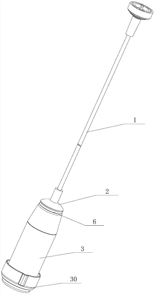
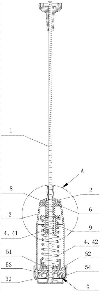
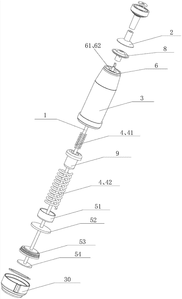
[0053] Such as figure 2 , image 3 , Figure 6 and Figure 10 As shown, the damping sleeve 8 described in this embodiment is arranged between the upper bracket 2 and the bracket 6, and the damping sleeve 8 includes a tray 81 supporting the upper bracket 2, which is located under the tray 81 and extends into the To the support sleeve 82 in the bracket 6 and the hanger installation hole 83 axially penetrating the tray 81 and the support sleeve 82 . The damping sleeve 8 is a damping rubber sleeve with a T-shaped integral structure as a whole.

[0054] Further, such as Figure 4 As shown, the pallet 81 is provided with a first variable damping structure 10 that makes the inner diameter of the boom installation hole 83 smaller after being stressed, and the first variable damping structure 10 is arranged on the upper end surface of the pallet 81 to support the upper bracket 2, and The downward pressure of the support 2 is converted into the radial deformation pressure of the d...

Embodiment 2

[0060] Such as Figure 8 and Figure 11 As shown, the damping sleeve 8 described in this embodiment is arranged between the bracket 6 and the pressure buffer mechanism, and the pressure buffer mechanism includes an upper spring seat 7, a damping spring 4 and a lower spring seat 5, and The vibrating spring 4 is installed between the upper spring seat 7 and the lower spring seat 5, and the damping sleeve 8 includes a tray 81 supporting the bracket 6, a support sleeve 82 arranged below the tray 81 and extending into the upper spring seat 7 and Axially penetrates the suspension rod installation hole 83 of the tray 81 and the support sleeve 82 . The damping sleeve 8 is a damping rubber sleeve with a T-shaped integral structure as a whole.

[0061] Further, the pallet 81 is provided with a first variable damping structure 10 that makes the inner diameter of the boom mounting hole 83 smaller after being stressed (see Figure 4 ), the first variable damping structure 10 is set on t...

Embodiment 3

[0067] This embodiment is the combination of embodiment one and embodiment two, such as Figure 9 As shown, a damping sleeve 8 is provided between the upper bracket 2 and the bracket 6, and between the bracket 6 and the pressure buffer mechanism.


PUM


Abstract

The invention discloses a variable-damping vibration-reduction device of a washing machine and the washing machine. The variable-damping vibration-reduction device comprises a hanging rod, an upper support, a sleeve pipe and a pressure buffer mechanism arranged in the sleeve pipe. The upper end of the sleeve pipe is provided with a bracket. The hanging rod penetrates through the upper support and the bracket and stretches into the sleeve pipe to be connected to the pressure buffer mechanism. At least one set of damping sleeves is arranged between the upper support and the pressure buffer mechanism. Damping sleeves provide variable damping force to the hanging rod. When the washing machine starts to operate in a dehydration manner with excessive large uneven load, an outer drum applies eccentric force to the damping sleeves. The damping sleeves deform in a radial direction to extrude the hanging rod so that the damping force becomes larger. The machine continues to operate in a dehydrated manner and the partial load becomes smaller. The eccentric force of the outer drum applied to the damping sleeves is released. The damping sleeves restore and damping force becomes smaller. The variable-damping vibration-reduction device of the washing machine and the washing machine have the following beneficial effects: the elasticity coefficient of the hanging rod is stably and smoothly changed so that vibration-reduction performance is improved; working noise is reduced; and vibration-reduction effect is enhanced.

Description

technical field [0001] The invention relates to the technical field of washing machines, in particular to a vibration damping device for a washing machine, in particular to a variable damping vibration reduction device for a washing machine and a washing machine using the vibration reduction device. Background technique [0002] Existing washing machines are divided into pulsator washing machines and drum washing machines. The structure of the pulsator washing machine includes: a shell forming the appearance of the washing machine; an outer shell that is suspended and fixed by a supporting member and used to accommodate washing water is provided inside the shell; Barrel; rotatably installed inside the outer barrel and an inner barrel with an agitator at the bottom; a driving motor installed on the lower side of the outer barrel and used to generate the driving force of the agitator and the inner barrel; used to drive the driving force of the driving motor The power transmiss...

Claims


Application Information

Patent Timeline
IPC IPC(8): D06F37/24
CPCD06F37/20
Inventor 吕佩师杨林张刚金田云高升成
Owner HEFEI HAIER WASHING MACHINE
Why Eureka
Try Eureka