
Air purification treatment device

A technology of a gas purification device and a processing device, which is applied in the field of air purification, can solve the problems of poor purification effect of the air purification device, unable to meet the needs of restaurant air purification, and limited volume of purified air, so as to reduce secondary pollution and achieve fast processing speed. , the effect of large inhalation volume

Inactive Publication Date: 2017-07-07
BEIJING GOLDEN SPRING TECH DEV
View PDF6 Cites 1 Cited by
  • Summary
  • Abstract
  • Description
  • Claims
  • Application Information

AI Technical Summary

Problems solved by technology

[0003] However, the existing air purification devices have poor purification effect, and the volume of purified air per unit time is limited, which cannot meet the needs of air purification in restaurants, meeting rooms and sports venues

Method used


Image

  • Air purification treatment device
  • Air purification treatment device
  • Air purification treatment device

Examples


Embodiment 2

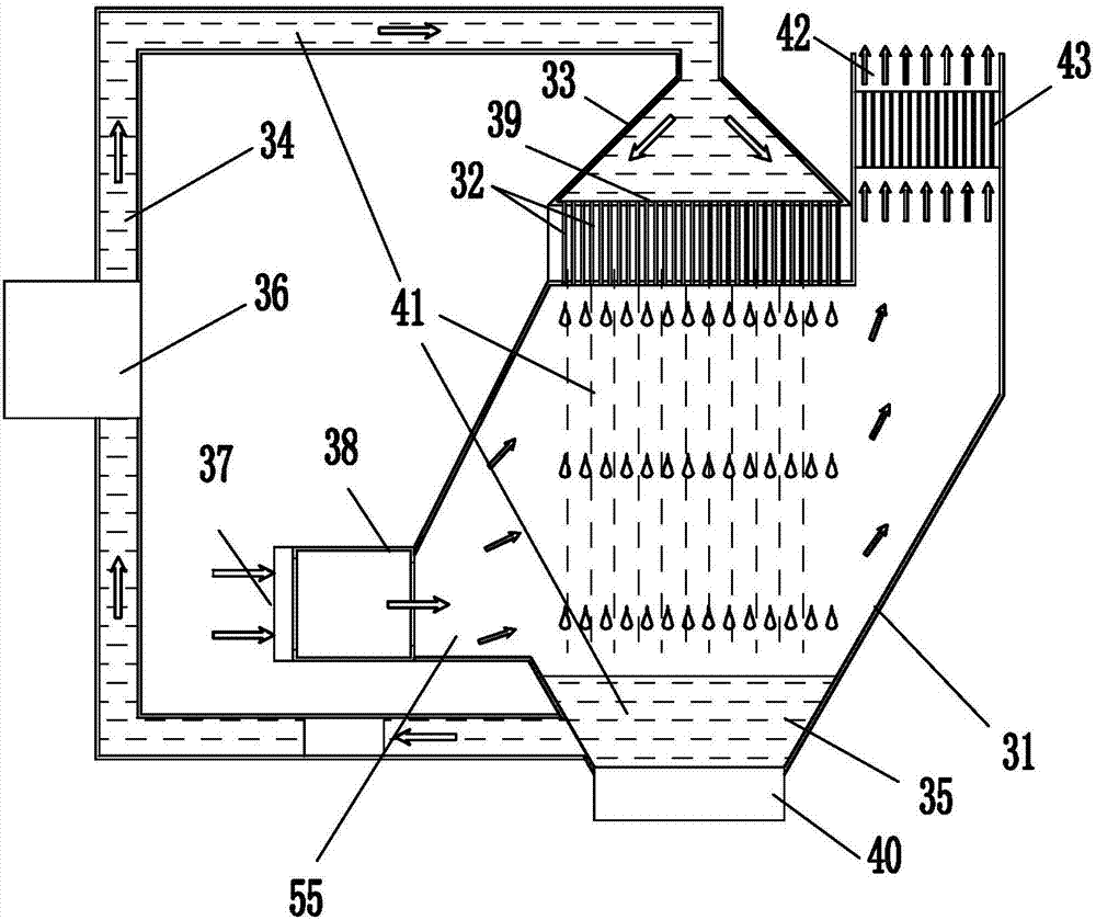
[0058] attached figure 2 It can be seen that an air purification treatment device includes an air filter device, and the air filter device is a cylindrical filter body 31;

[0059] The cross-sectional area of ​​the right end face of the increase decompression chamber 55 is greater than the cross-sectional area of ​​the left end face; the cross-sectional area of ​​the increase decompression chamber 55 gradually increases from left to right; when the air flow flows through the increase decompression chamber, As the cross-sectional area of ​​the increasing decompression chamber increases, the air pressure is reduced; allowing the airflow to enter the connecting pipe smoothly.

[0060] A spray device is arranged above the cylindrical filter body 31;

[0061] Described shower device comprises the shower pipe 32 that is arranged in vertical direction;

[0062] The spray pipe 32 is connected with the liquid purification pool 35 arranged at the bottom of the filter tank through the...

Embodiment 3

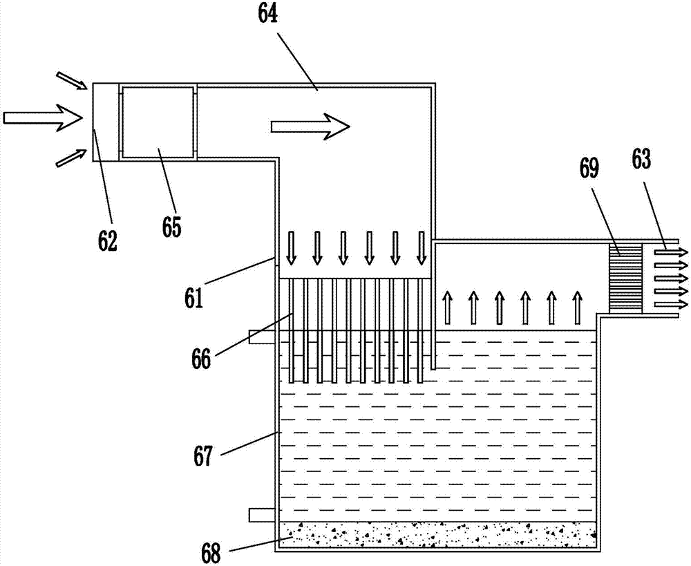
[0075] attached image 3 It can be seen that an air purification treatment device includes an air filter device, the air filter device is a filter tank body 61, the air filter device includes an air inlet 62 and an exhaust port 63, and the air inlet 62 is along the horizontal direction Set, the exhaust port 63 is set along the horizontal direction;

[0076] The augmented decompression chamber is in the shape of a right angle, including a horizontal part and a vertical part;

[0077] The cross-sectional area of ​​the horizontal portion is smaller than the cross-sectional area of ​​the vertical portion;

[0078] A blower 65 is provided at the opening of the left end of the horizontal part;

[0079] The open end of the vertical part is downward; the opening of the vertical part is provided with a communication pipe 66;

[0080] The connecting pipes form multiple air paths spaced apart from each other; the air is divided into multiple paths after passing through the connecting ...


PUM


Abstract

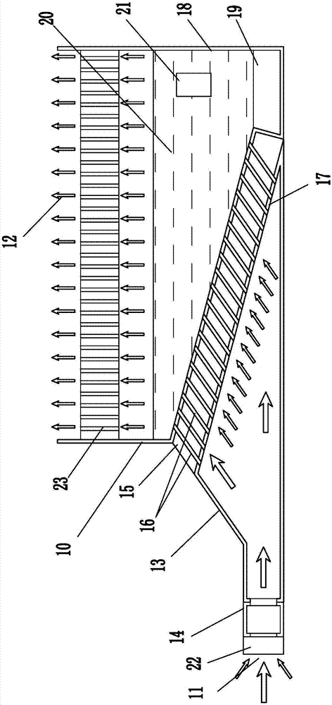
The invention relates to an air purification treatment device. The air purification treatment device comprises an air filtering device; the air filtering device comprises an air inlet and an air outlet, and the air inlet is connected with the air outlet through an amplification decompression chamber and a gas purification device; the amplification decompression chamber is a cavity; the cross sectional area of the end surface of a gas outlet of the cavity is larger than that of the end surface of a gas inlet; the cross sectional area of the amplification decompression chamber is gradually increased from the inlet to the outlet; and an air blower is arranged at the gas inlet of the amplification decompression chamber. The air purification treatment device is large in air suction amount and high in one-time processing speed; a solid and liquid mixing treatment mode is adopted, the filtering effect is good, filtered impurities can be directly treated, the cost is reduced, and the secondary pollution to the environment is reduced; the air blower adopts an air floating bearing, and therefore the air inlet speed is accurately controlled, oil mixing is avoided, and high speed, no friction force, no abrasion, no noise and anti-collision protection are achieved; and filtering and humidifying are carried out simultaneously so that high-quality air can be provided.

Description

technical field [0001] The invention relates to the field of air purification, in particular to an air purification treatment device. Background technique [0002] With the development of industrialization in our country, the air quality is gradually deteriorating. In recent years, there have been frequent large-scale smog across the country, especially the severe smog that has continued after the beginning of winter this year, which seriously threatens human health. It is urgent to control smog and purify the air. Although the country has issued a series of long-term strategic guidelines to reduce the impact of smog, for the current urban air conditions in dry and cold areas, direct air purification is still the most effective way. [0003] However, the existing air purification devices have poor purification effect, and the volume of purified air per unit time is limited, which cannot meet the needs of air purification in restaurants, meeting rooms and sports venues. Con...

Claims


Application Information

Patent Timeline
Patent Type & Authority Applications(China)
IPC IPC(8): F24F1/02F24F13/28F24F13/00F24F6/12B01D50/00
CPCF24F1/02F24F6/12F24F13/00F24F13/28B01D50/60
Inventor 张晓冬
Owner BEIJING GOLDEN SPRING TECH DEV
Learn More