Directly-heated type heat pump water heater

A heat pump water heater, direct heating technology, applied in fluid heaters, lighting and heating equipment, etc., can solve the problems of large material cost and time cost, heat loss, etc., to achieve recycling, energy saving, energy saving The effect of recycling

Inactive Publication Date: 2017-07-07
HUNAN CHUANGHUA LOW CARBON ENVIRONMENTAL PROTECTION TECH
View PDF7 Cites 4 Cited by
  • Summary
  • Abstract
  • Description
  • Claims
  • Application Information

AI Technical Summary

Problems solved by technology

[0006] The direct heating heat pump water heater in the prior art needs to be equipped with a four-way valve, and the evaporator is generally installed outdoors to absorb the outdoor air energy. In case of cold weather and frost, it is also necessary to set a defrosting program to eliminate the possibility of frost formation. impact, the material cost and time cost are relatively large, and further, in the process of bathing, the heat contained in the generated water vapor is often lost in vain due to unused

Method used


Image

  • Directly-heated type heat pump water heater
  • Directly-heated type heat pump water heater
  • Directly-heated type heat pump water heater

Examples


no. 1 example

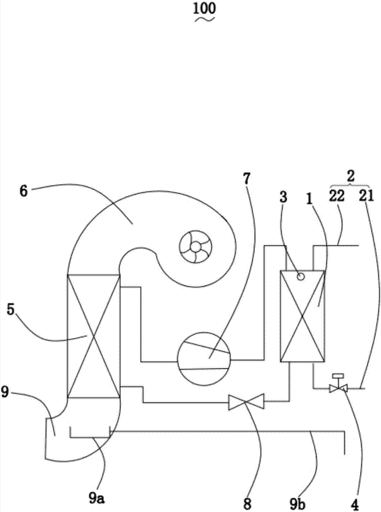
[0035] The present invention proposes a direct heating heat pump water heater 100 for heating bath water.

[0036] Please refer tofigure 1 , in one embodiment of the present invention, the direct heating heat pump water heater 100 includes a condenser 1, an evaporator 5, a compressor 7 and a throttling device 8 respectively connected to the two ends of the evaporator 5 and the condenser 1, and is used to extract water from the bathroom. Water vapor enters the air extraction device 6 of the evaporator 5 , the water side passage pipe 2 arranged on the condenser 1 and the control valve 4 arranged on the water side passage pipe 2 .

[0037] The condenser 1 is used to directly heat the bathing water, and can store a certain capacity of bathing water inside, and release heat energy by condensing the gaseous working fluid into a liquid working fluid, so as to achieve the purpose of heating the bathing water.

[0038] The water side channel pipe 2 is used to input bath water to be hea...

no. 2 example

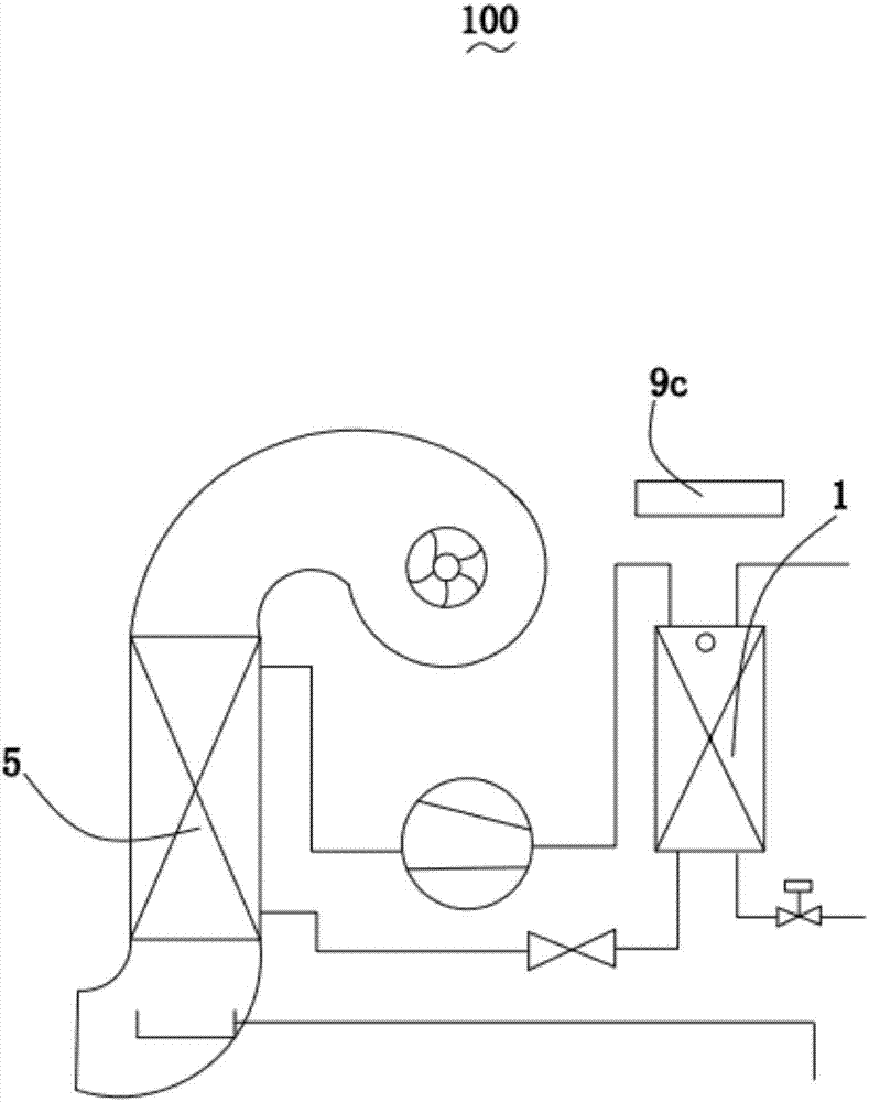
[0057] The present invention proposes a direct heating heat pump water heater 100 for heating bath water.

[0058] Please refer to figure 2 The difference between this embodiment and the first embodiment is that the direct heating heat pump water heater 100 further includes a first thermal energy compensation device 9c for increasing the ambient temperature of the evaporator 5 and / or the condenser 1 .

[0059] In this embodiment, the first thermal energy compensation device 9 c is arranged adjacent to the condenser 1 .

[0060] Of course, in other embodiments, the first thermal energy compensating device 9c may also be located in other suitable positions, it only needs to be able to increase the ambient temperature of the evaporator 5 and / or the condenser 1 .

[0061] In this embodiment, the first thermal energy compensation device 9c may be a bathroom heater.

[0062] Of course, in other embodiments, the first thermal energy compensating device 9c may also be other heating...

no. 3 example

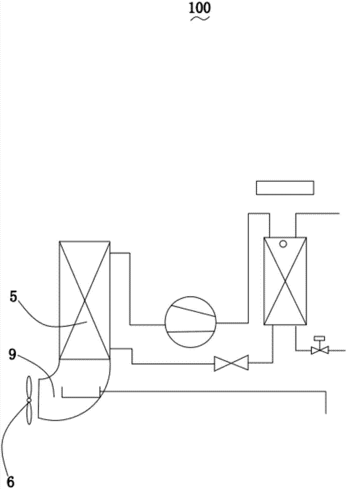
[0067] The present invention proposes a direct heating heat pump water heater 100 for heating bath water.

[0068] Please refer to image 3 The difference between this embodiment and the first embodiment is that the air extraction device 6 is an axial flow fan, and the axial flow fan is arranged adjacent to the air outlet pipe 9, so as to achieve more effective extraction of water vapor into the evaporator 5.


PUM


Abstract

The invention discloses a directly-heated type heat pump water heater used for heating bath water and comprising an evaporator, a condenser, a compressor, a throttling device, air exhausting device, a water side channel pipe and a controlling valve. The compressor and the throttling device communicate with the evaporator and the two ends of the condenser correspondingly; the air exhausting device is used for extracting water vapor in a bathroom into the evaporator; the water side channel pipe is arranged on the condenser, and the controller valve is arranged on the water side channel pipe. According to the provided directly-heated type heat pump water heater, water vapor latent heat is absorbed to heat the bath water, and accordingly heat energy circulation is achieved better.

Description

technical field [0001] The invention relates to the technical field of water heaters, in particular to a direct heating heat pump water heater. Background technique [0002] At present, there is a long way to go for human beings to save energy and reduce emissions. The greenhouse effect has caused the Nor Nino phenomenon to become increasingly prominent, and the smog that endangers human health and affects the growth of crops is becoming more and more serious. Vigorously advocating the research and development of energy-saving advanced technologies and giving full play to resource recycling are the priority development directions of today's economy. There is no doubt that this is the policy orientation that the Chinese government will uphold for a long time to come. [0003] With the development of the national economy and the continuous improvement of people's living standards, the demand for domestic hot water is increasing, and the consumption of energy is increasing day ...

Claims


Application Information

Patent Timeline
Patent Type & Authority Applications(China)
IPC IPC(8): F24H4/02F24H9/20
CPCF24H4/02F24H9/2007
Inventor 刘小江陈发明向立平
Owner HUNAN CHUANGHUA LOW CARBON ENVIRONMENTAL PROTECTION TECH
Why Eureka
Try Eureka