Equipment testing method and device applied to thermal power plant

A technology of equipment testing and testing devices, which is applied in the direction of measuring devices, material defect testing, and optical testing for flaws/defects. The effect of saving labor cost

Pending Publication Date: 2017-07-07
陕西清水川能源股份有限公司
View PDF19 Cites 17 Cited by
  • Summary
  • Abstract
  • Description
  • Claims
  • Application Information

AI Technical Summary

Problems solved by technology

In the prior art, detection is usually done by manpower, which is time-consuming, laborious and inefficient. Especially for large boilers with large capacity and size, it is relatively difficult to detect them manually. Long time, high labor cost and unsafe

Method used


Image

  • Equipment testing method and device applied to thermal power plant
  • Equipment testing method and device applied to thermal power plant
  • Equipment testing method and device applied to thermal power plant

Examples


Embodiment 1

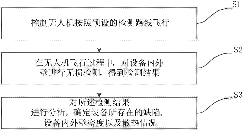
[0036] figure 1 It shows a schematic flowchart of an equipment detection method applied to a thermal power plant provided by Embodiment 1 of the present invention. Such as figure 1 As shown, the device detection method includes:

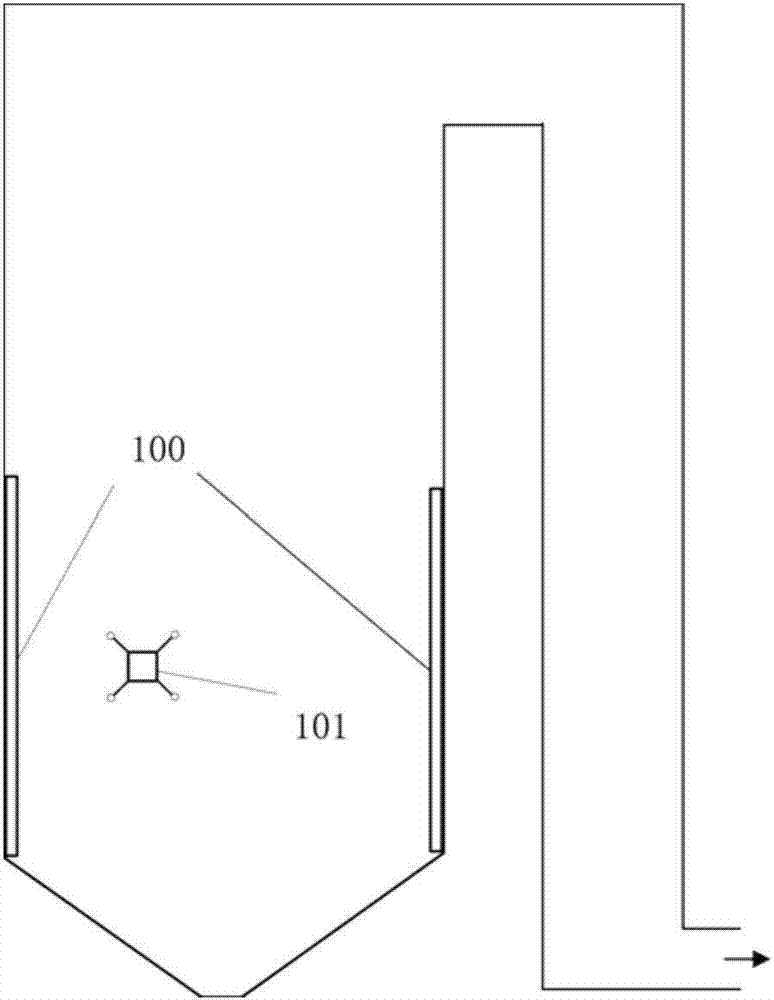
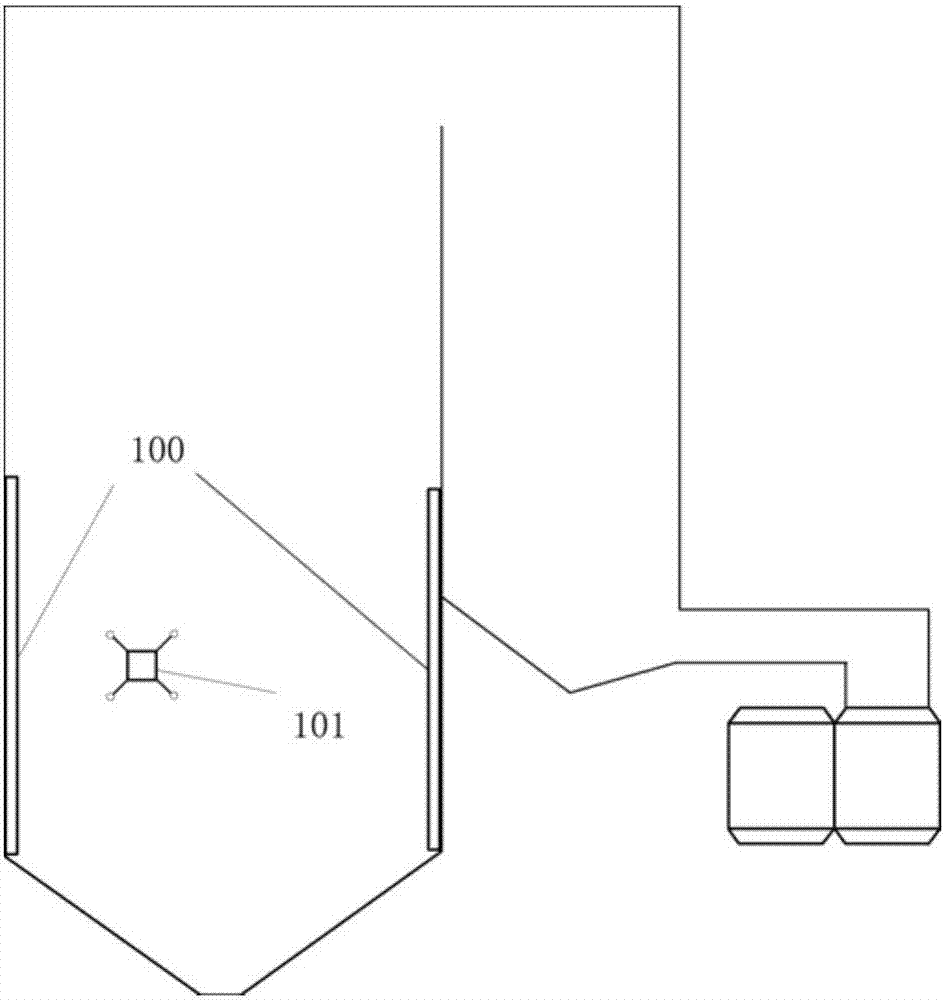
[0037] Step S1, controlling the UAV 101 to fly according to a preset detection route;

[0038] Step S2, during the flight of the UAV 101, conduct non-destructive testing on the inner and outer walls of the equipment, and obtain the testing results, wherein the equipment includes a boiler, a chimney 200, a desulfurization absorption tower 300 and an air cooling island;

[0039] Step S3, analyzing the detection results to determine the defects existing in the equipment, the density of the inner and outer walls of the equipment, and the heat dissipation.

[0040] The technical scheme of the present embodiment is specifically:

[0041] Step S1, controlling the UAV 101 to fly according to a preset detection route.

[0042] Wherein, the detection rout...

Embodiment 2

[0056] Corresponding to Embodiment 1 of the present invention, Figure 8 A schematic structural diagram of an equipment detection device applied to a thermal power plant provided by an embodiment of the present invention is shown. Such as Figure 8 As shown, an equipment detection device applied to a thermal power plant includes: an unmanned aerial vehicle 101, a control device 102, a detection device 103, a data analysis device 104, and a lighting device 105; wherein, as Figure 4 As shown, the detection device 103 and the lighting device 105 are both installed on the drone 101 .

[0057] Preferably, the control device 102 is a radio remote controller, which is used to control the UAV 101 to fly according to a preset detection route, control the detection device 103 to perform non-destructive testing on the inner and outer walls of the equipment, and control the lighting device 105 to Lighting during inspection. Wherein, the detection route is preset according to the posit...


PUM


Abstract

The invention discloses an equipment testing method and device applied to a thermal power plant. The method comprises the steps of controlling an unmanned aerial vehicle to fly according to a preset testing route; collecting terahertz images or infrared images of inner and outer walls of thermal power plant equipment in the flight process of the unmanned aerial vehicle, wherein the thermal power plant equipment comprises a boiler, a chimney, a desulfurizing absorption tower and an air cooling island; and analyzing the terahertz images or the infrared images and determining the position of the defect of the equipment and the heat dissipation condition. The defects of the inner and outer walls of the thermal power plant equipment are detected by using the unmanned aerial vehicle instead of manpower, so that the human cost can be reduced, the time can be saved, and the testing efficiency is improved.

Description

technical field [0001] The invention relates to the technical field of equipment detection, in particular to an equipment detection method and device applied to thermal power plants. Background technique [0002] Thermal power units account for more than 60% of my country's power generation. Due to the low efficiency and environmental protection of small thermal power units, my country has shut down 90% of small thermal power units in recent years according to national conditions, and modern large-scale units also undertake 6%. Ten power generation. Boilers, chimneys, desulfurization absorption towers, air-cooling islands and other equipment in thermal power plants will produce plane defects such as cracks, metal delamination, scaling, and wear for a long time, which will affect the operation of the equipment, so the detection of equipment is particularly important. In the prior art, detection is usually done by manpower, which is time-consuming, laborious and inefficient. E...

Claims


Application Information

Patent Timeline
Patent Type & Authority Applications(China)
IPC IPC(8): G01N21/95G01N21/88G01N25/72
CPCG01N21/8806G01N21/95G01N25/72
Inventor 侯思明
Owner 陕西清水川能源股份有限公司
Why Eureka
Try Eureka