
Rotating-reflection-surface-based imaging method and system of mirroring synthetic aperture radiometer

A technology of rotating reflection and synthetic aperture, which is applied in the direction of radio wave reflection/re-radiation, using re-radiation, radio wave measurement system, etc., can solve the problems of high system complexity, improve the resolution of scene brightness temperature images, reduce The effect of number of antennas, size reduction and weight reduction

Active Publication Date: 2017-07-07
HUAZHONG UNIV OF SCI & TECH
View PDF2 Cites 10 Cited by
  • Summary
  • Abstract
  • Description
  • Claims
  • Application Information

AI Technical Summary

Problems solved by technology

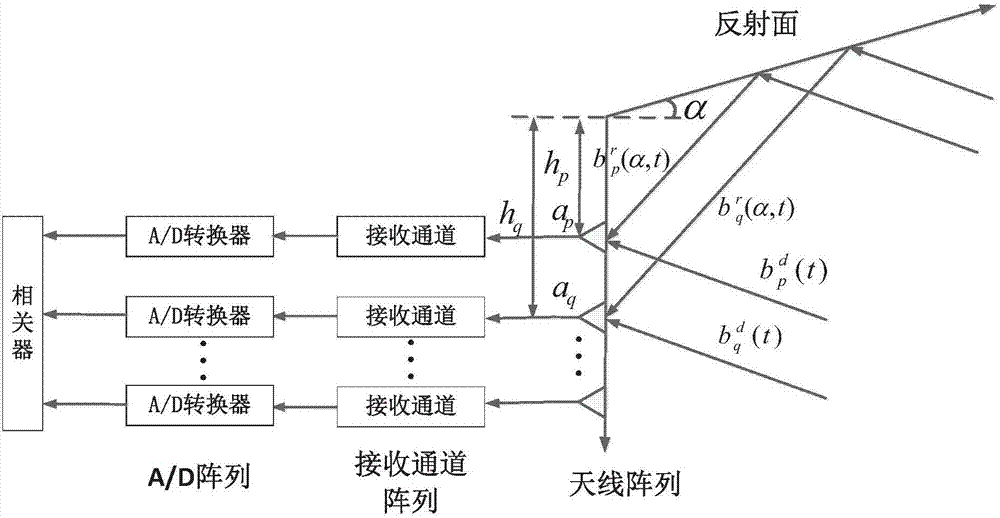
[0004] In view of the above defects or improvement needs of the prior art, the present invention provides a mirrored synthetic aperture radiometer and imaging method and system based on a rotating reflector, the purpose of which is to reduce the number of antennas and improve the resolution of the scene brightness temperature image, thereby Solve the technical problems of large number of antennas and high system complexity under the required scene brightness temperature image resolution

Method used


Image

  • Rotating-reflection-surface-based imaging method and system of mirroring synthetic aperture radiometer
  • Rotating-reflection-surface-based imaging method and system of mirroring synthetic aperture radiometer
  • Rotating-reflection-surface-based imaging method and system of mirroring synthetic aperture radiometer

Examples


Embodiment 1

[0092] Example 1: Brightness temperature image of the scene obtained when N=4

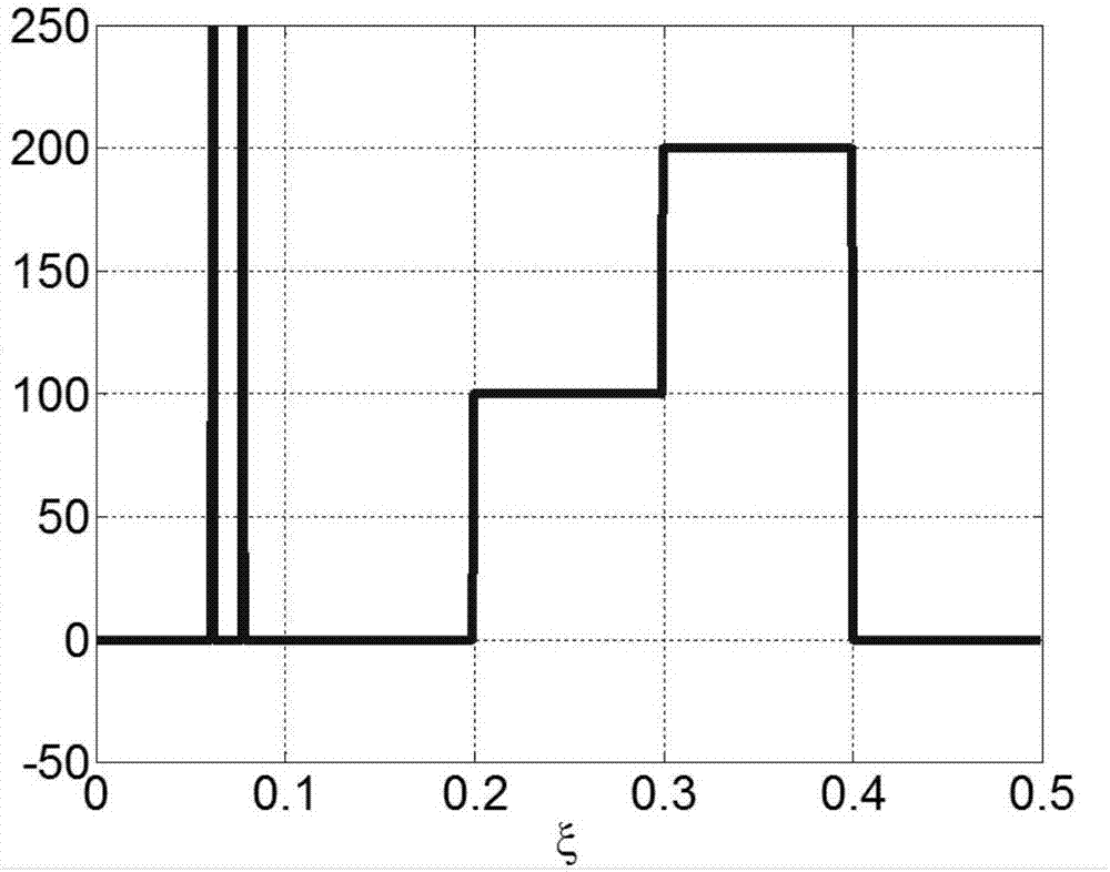
[0093] In this embodiment, for the antenna array, four antennas are arranged as a one-dimensional linear array, the distance between the antennas is {3λ, 19λ, 11λ}, and the distances between the reflecting surface and the first antenna of the antenna array are 2λ, 42λ, 102 lambda. image 3 The ideal scene brightness temperature image for testing is composed of two very close point sources and one extended source. The point source is used to test the resolution, and the extended source is used to simulate land, ocean, and cold air.

[0094] Specific steps are as follows:

[0095] (1) For a four-antenna array, set the distance between the reflective surface and the first antenna of the antenna array as 2λ, and the initial inclination angle between the reflective surface and the array as 1 degree, obtain the cross-correlation function and discretize it, and combine all the two antennas The cross-cor...

Embodiment 2

[0101] Example 2: The scene brightness temperature image obtained when N=1

[0102] For a single antenna, the distances between the reflective surface and the antenna are 200λ, 230λ, and 300λ, respectively. image 3 The ideal scene brightness temperature image for testing is composed of two very close point sources and one extended source. The point source is used to test the resolution, and the extended source is used to simulate land, ocean, and cold air.

[0103] Specific steps are as follows:

[0104] (1) For a single antenna, the distance between the reflective surface and the antenna is set to be 200λ, and the initial inclination angle between the reflective surface and the normal direction of the plane where the antenna is located is 1 degree, and the autocorrelation function is obtained and discretized to obtain the matrix equation;

[0105] (2) Rotate the reflective surface by 0.02 degrees each time until 5 degrees. After each rotation, a new matrix equation is obtai...


PUM


Abstract

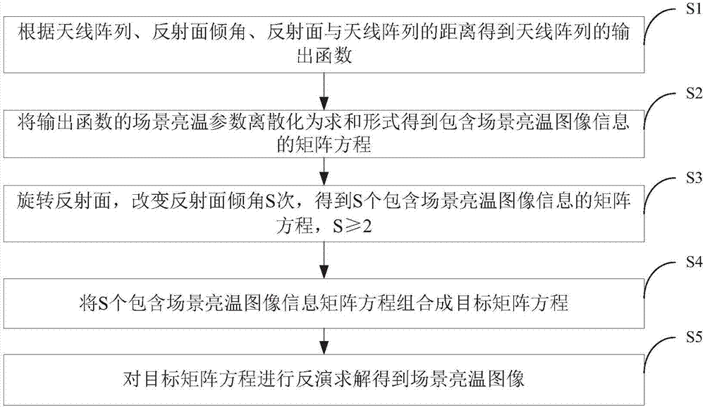
The invention discloses a rotating-reflection-surface-based imaging method and system of a mirroring synthetic aperture radiometer. The method comprises: according to an antenna array, a reflection surface angle, and a distance between the reflection surface and the antenna array, an output function of the antenna array is obtained; a scene brightness temperature of the output function is discretized into a summation form to obtain a matrix equation containing scene brightness temperature image information; the reflection surface is rotated and the inclination angle of the reflection surface is changed by S times to obtain S matrix equations containing the scene brightness temperature image information, wherein the S is larger than or equal to 2; the S matrix equations containing the scene brightness temperature image information are combined into a target matrix equation; and the target matrix equation is inversed to obtain a scene brightness temperature image. The larger the frequency of rotation of the reflection surface, the smaller the angle of the rotation each time; and the larger the combined target matrix equation, the higher the scene brightness temperature image quality.

Description

technical field [0001] The invention belongs to the field of microwave remote sensing and detection technology, and more specifically relates to an imaging method and system based on a rotating reflector-based mirror synthetic aperture radiometer, which can be applied to remote sensors for earth remote sensing, lunar remote sensing, and deep space exploration. Background technique [0002] The synthetic aperture radiometer synthesizes multiple small antennas into an equivalent large antenna aperture, and arranges them in a sparse array, which reduces the weight and volume of the antenna, and solves the inherent contradiction between resolution and aperture size. But this advantage comes at the cost of system structure and signal processing complexity, especially in large synthetic aperture radiometer systems, such as spaceborne synthetic aperture radiometers. [0003] Mirrored aperture synthetic radiometers can be used to reduce the number of antenna elements or to increase ...

Claims


Application Information

Patent Timeline
IPC IPC(8): G01S13/90
CPCG01S13/904G01S3/02
Inventor 李青侠窦昊锋桂良启陈柯李育芳黄聪聪胡孟林
Owner HUAZHONG UNIV OF SCI & TECH
Learn More