
Internal serial interface

A serial interface and interface technology, applied in climate sustainability, instruments, electrical digital data processing, etc., can solve problems such as consumption and less routing resources

Active Publication Date: 2017-07-07
SKYWORKS SOLUTIONS INC
View PDF6 Cites 2 Cited by
  • Summary
  • Abstract
  • Description
  • Claims
  • Application Information

AI Technical Summary

Problems solved by technology

Additionally, there is a need for slave devices with serial interfaces that consume fewer routing resources and do not require additional slave addresses, register maps, and / or pins

Method used


Image

  • Internal serial interface
  • Internal serial interface
  • Internal serial interface

Examples


Embodiment Construction

[0033] Headings, if any, are provided herein for convenience only and do not necessarily affect the scope or meaning of the claimed invention.

[0034] Various non-limiting examples of devices and methods for use with serial interfaces are provided herein.

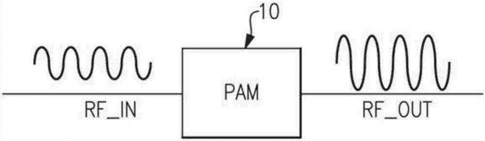
[0035] figure 1 is a schematic diagram of a power amplifier module for amplifying radio frequency (RF) signals. The illustrated power amplification module (PAM) 10 may be configured to amplify a radio frequency signal IN to generate an amplified radio frequency signal OUT. As described herein, a power amplification module may include one or more power amplifiers.

[0036] Radio frequency power amplifiers can be used to boost the power of radio frequency signals having relatively low power. Thereafter, the boosted RF signal can be used for a variety of purposes, including driving the transmitter's antenna.

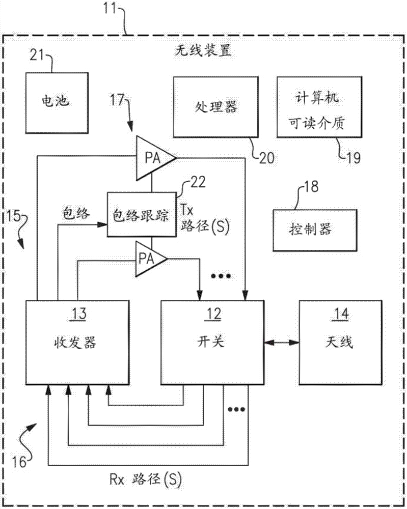
[0037] Power amplifiers may be included in mobile phones to amplify radio frequency signals for transmission. Fo...


PUM


Abstract

A simplified serial interface for a communications device. The serial interface includes an RF front end and a transmit block and at least one receive block located on different dies. The receive block is activated by a clock generator that is separate than the system clock. The at least one receive block can inhibit transmission of an enable signal to the receive block and inhibit operation of an oscillator of the interface.

Description

technical field [0001] Embodiments of the present invention relate to electronic systems, and in particular, to serial interfaces of electronic communication devices and systems. Background technique [0002] Radio Frequency Front Ends (RFFEs) used in conjunction with devices such as smartphones, tablets, computers, etc. are increasingly required to have more control states that further require control of additional peripheral or downstream devices. Typically, the added control state for controlling additional peripherals is accomplished using a standard general purpose input output (GPIO) interface or a standard serial MIPI RFFE type interface. [0003] However, these interfaces consume a lot of IC resources. For example, increasing the amount of GPIO semaphores requires more real estate on the master and slave chips using wire-bond connections. This problem is particularly prominent for flip chip (flip chip style dies). In addition, this approach also leads to larger ro...

Claims


Application Information

Patent Timeline
Patent Type & Authority Applications(China)
IPC IPC(8): G06F13/38G06F13/42
CPCG06F13/382G06F13/4291G06F13/4022G06F13/4286Y02D10/00
Inventor J.H.罗斯M.L.巴诺维茨
Owner SKYWORKS SOLUTIONS INC
Features
  • Generate Ideas
  • Intellectual Property
  • Life Sciences
  • Materials
  • Tech Scout
  • Unparalleled Data Quality
  • Higher Quality Content
  • 60% Fewer Hallucinations
Learn More