
A fuel rod automatic compression spring device

A technology of fuel rods and compression springs, which is applied in the field of automatic fuel rod compression spring devices, can solve problems such as low production efficiency and unstable product quality, and achieve the effects of easy operation, reduced waste rate of compression springs, and improved product quality

Active Publication Date: 2019-07-12
中国原子能工业有限公司
View PDF5 Cites 0 Cited by
  • Summary
  • Abstract
  • Description
  • Claims
  • Application Information

AI Technical Summary

Problems solved by technology

[0006] In view of the above prior art, the present invention provides an automatic fuel rod compression spring device to solve the problems of low production efficiency and unstable product quality in the prior art.

Method used


Image

  • A fuel rod automatic compression spring device
  • A fuel rod automatic compression spring device
  • A fuel rod automatic compression spring device

Examples


Embodiment Construction

[0035] The present invention will be described in detail below in conjunction with the accompanying drawings and specific embodiments.

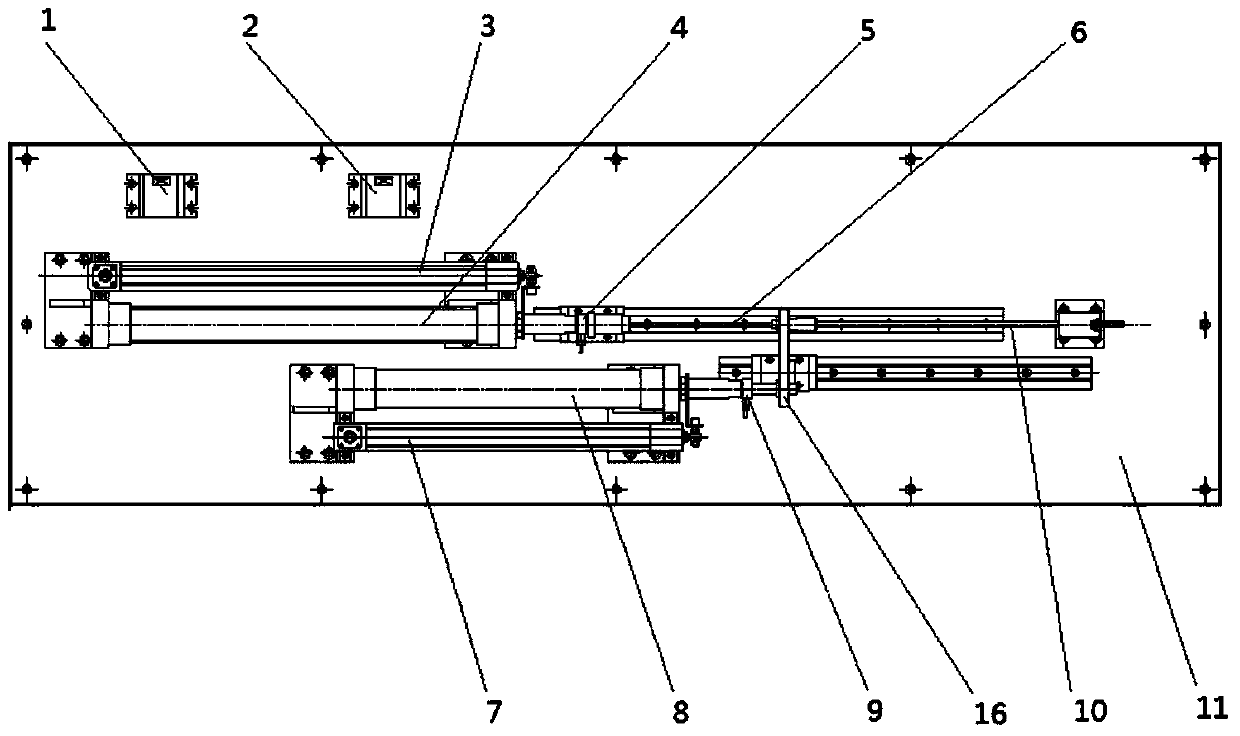
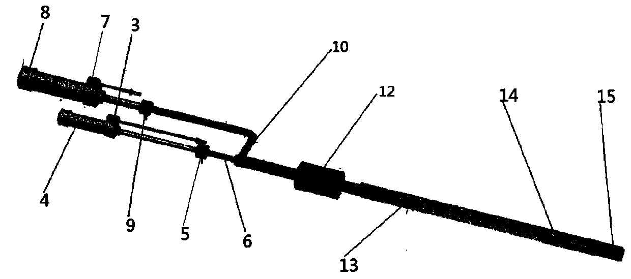
[0036] Such as figure 1 and figure 2 As shown, an automatic fuel rod compression spring device of the present invention includes a length measuring mechanism, a compression spring mechanism, a base plate 11, a guide sleeve 12 and a connecting handle 16;

[0037] The length-measuring mechanism includes a length-measuring electric control valve 1, a length-measuring displacement sensor 3, a length-measuring cylinder 4, a length-measuring pressure sensor 5 and a length-measuring ejector rod 6; 3 is set on the length-measuring cylinder 4 to record the displacement of the length-measuring mandrel 6, and the length-measuring pressure sensor 5 is set on the axis of the length-measuring cylinder 4 to record the force transmitted by the length-measuring mandrel 6 from the core block 14 the pressing force;

[0038] The compression spring mechanism ...


PUM


Abstract

The invention relates to the technical field of fuel component manufacturing, in particular to an automatic fuel rod spring compressing device and an automatic fuel rod spring compressing method. The automatic fuel rod spring compressing device comprises a length testing mechanism, a spring compressing mechanism, a substrate, a guide sleeve and a connecting handle, wherein the spring compressing mechanism is fixedly connected with the length testing mechanism through the connecting handle; the spring compressing mechanism and the length testing mechanism are arranged on the substrate; the guide sleeve is arranged on the substrate; the guide sleeve is used for fixing and limiting the spring compressing mechanism and the length testing mechanism. The automatic fuel rod spring compressing method comprises the following steps: measuring displacement of a core block by using the length testing mechanism, further measuring pretightening force to the core block, compressing a spring into a fuel rod casing by using the spring compressing mechanism, tightly compressing the spring, and simultaneously measuring the compression intensity of the spring and the pretightening force to the spring. By adopting the device and the method, the productivity and the product quality level are greatly increased, the rejection rate of compressed springs is reduced to be approximate to 0, meanwhile the spring compression operation process is simplified, and the working intensity of operators is alleviated.

Description

technical field [0001] The invention relates to the technical field of fuel assembly manufacturing, in particular to a fuel rod automatic compression spring device and a fuel rod automatic compression spring method. Background technique [0002] The existing fuel rod compression spring device needs to be completed when compressing the spring: manually put the spring into the rotating disk → the probe rod presses the core block → measure the origin → the probe rod withdraws → the rotating disk rotates → the probe rod is pushed into the spring → 100% by a special person Manual adjustment and inspection. The whole process is time-consuming and cumbersome. Moreover, when the "probing rod is pushed into the spring", the centering performance is not good due to the defect in the machining accuracy of the spring positioning rotating disc. If the spring hole cannot be accurately controlled to the position of the axial centerline of the spring device, it is easy to be biased. The s...

Claims


Application Information

Patent Timeline
Patent Type & Authority Patents(China)
IPC IPC(8): G21C21/02
CPCG21C21/02Y02E30/30
Inventor 郭彦戈尤勇陈德华杨通高齐世金
Owner 中国原子能工业有限公司
Learn More