Planar array antenna and array method thereof

A planar array antenna and array technology, which is applied in the direction of manufacturing antenna array devices, antennas, antenna arrays, etc., can solve the problems of scanning grating lobes and increasing the distance between antenna elements, so as to reduce the amount of operation, maintain polarization characteristics, The effect of reducing the difficulty of engineering realization

Inactive Publication Date: 2017-07-07
CHINA ELECTRONIC TECH GRP CORP NO 38 RES INST
View PDF5 Cites 8 Cited by
  • Summary
  • Abstract
  • Description
  • Claims
  • Application Information

AI Technical Summary

Problems solved by technology

[0005] The purpose of the present invention is to provide a planar array antenna and its array method to solve the problem of large active phased array antennas reducing the number of active components resulting in increased spacing between antenna elements and thus the occurrence of scanning grating lobes

Method used


Image

  • Planar array antenna and array method thereof
  • Planar array antenna and array method thereof
  • Planar array antenna and array method thereof

Examples


Embodiment Construction

[0024] The present invention will be described in detail below in conjunction with the accompanying drawings.

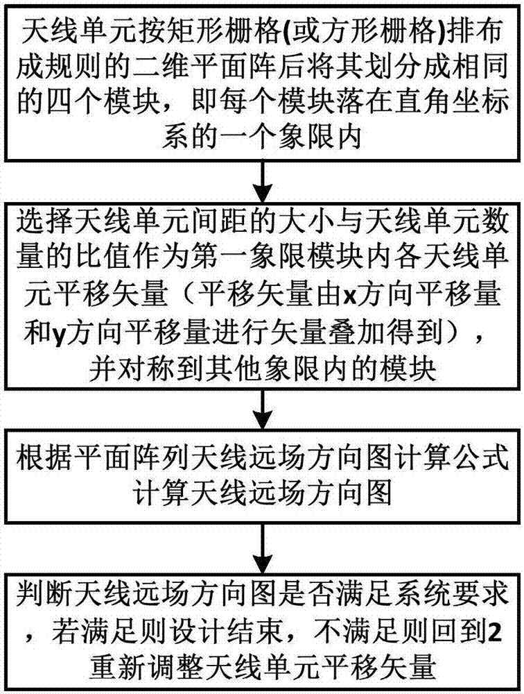
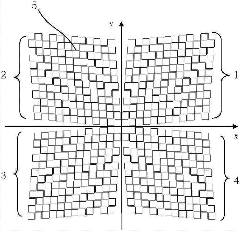
[0025] see figure 2 , the present invention takes the 24X24 array as an example to describe the technical solution of the invention in detail: a planar array that works in a certain band is arranged according to a square grid in the plane, and the unit spacing in the x direction of the antenna is 2 wavelengths, and the antenna in the y direction The spacing between the strip elements is 2 wavelengths, and the array is a planar array composed of 24 by 24 antenna elements. The front is divided into four array modules 1, 2, 3, 4, and the antenna unit 5 of the array module 1 falling in the first quadrant is vector shifted.

[0026] see image 3 , select the translation vector (x, y) as the translation vector of the antenna unit 5 of the array module 1 in the first quadrant, where x and y are respectively equal to 2 / 11 wavelength, and symmetric to the array modules 2, ...


PUM


Abstract

The invention relates to the field of the array antenna technology, particularly to a planar array antenna and an array method thereof. The antenna comprises four array modules; each array module is formed by array combination of a plurality of wire units; and the four array modules are arranged in four quadrants of a rectangular coordinate system. In the same quadrant, each two adjacent rows of antenna units deviate at a certain distance along a horizontal direction and each two adjacent columns of antenna units deviate at a certain distance along a longitudinal direction, so that all antenna units in the same quadrant are arranged in a quadrangle array manner; and the array modules in each two adjacent quadrants are arranged symmetrically relative to a coordinate axis between the adjacent two quadrants. All modules in the four quadrants are arranged symmetrically, so that the engineering implementation efficiency can be reduced; the antenna units in the antenna array only make translation instead of rotation, so that the original polarization characteristics of the antenna units are kept and thus antenna polarization synthesis can be realized.

Description

technical field [0001] The invention belongs to the technical field of array antennas, and in particular relates to a planar array antenna and an array method thereof. The invention can be used in an active phased array radar system. Background technique [0002] With the rapid development of active phased array radar technology, system requirements such as high power and high resolution guide the rapid development of active phased array antennas in the direction of electrical large size (electrical size is the physical size of the antenna relative to the size of the operating frequency wavelength ). The active phased array antenna changes the feeding phase of the antenna unit through active components (such as: delay amplification component, T / R component) to realize antenna array beam scanning. The scale of the antenna array continues to expand, and the number of antenna channels continues to increase, resulting in an increase in the number of active components. Due to t...

Claims


Application Information

Patent Timeline
IPC IPC(8): H01Q21/24H01Q21/00
CPCH01Q21/0087H01Q21/24
Inventor 孙立春侯田张洪涛汪伟郭文卓金谋平鲁加国
Owner CHINA ELECTRONIC TECH GRP CORP NO 38 RES INST
Why Eureka
Try Eureka