
Novel mounting equipment for external equipment of computer

A technology for installing equipment and computers. It is applied in the structural parts of electrical equipment, rack/frame structure, cooling/ventilation/heating renovation, etc. problems, to achieve scientific and reasonable design, ensure normal operation, and facilitate maintenance.

Inactive Publication Date: 2017-07-07
CHENGDU BOTAI TECH
View PDF0 Cites 1 Cited by
  • Summary
  • Abstract
  • Description
  • Claims
  • Application Information

AI Technical Summary

Problems solved by technology

Using this method to place the external equipment of the computer, the fixing effect is not good, and the ventilation effect between the upper and lower boards is not good, resulting in slow heat dissipation, which in turn affects the operation of the equipment
In addition, due to the inconsistent size and volume of various devices outside the computer, correspondingly different floor heights and installation locations are required
In addition, the external equipment of the computer has multiple connecting wires, which are placed in a cabinet, and the connecting wires are easy to be tangled, which is not convenient for maintenance and repair.
In the prior art, a dense computer peripheral device installation device with a cable organizer is provided, which can effectively solve the problems of poor fixing effect of the computer peripheral device installation device, unreasonable spatial layout, and easy entanglement of connecting wires
But this kind of computer external equipment installation device is only by not hindering the heat dissipation of computer external equipment itself and is radiated, when equipment power is bigger or installation is intensive, the heat dissipation effect is not good

Method used


Image

  • Novel mounting equipment for external equipment of computer
  • Novel mounting equipment for external equipment of computer

Examples


Embodiment

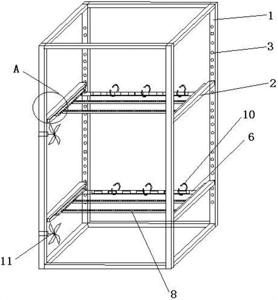
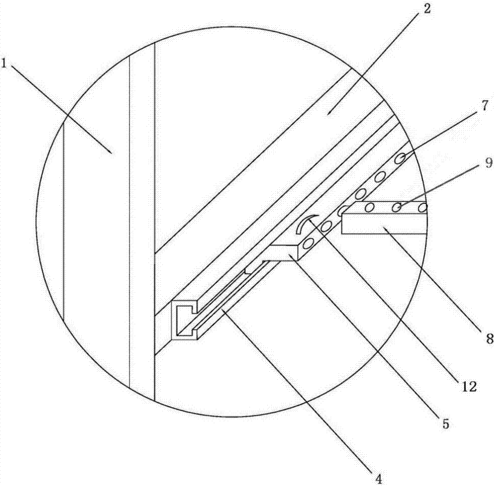
[0016] like figure 1 and 2 As shown, a new type of computer peripheral installation equipment includes a box-type main body support 1 with several layers and a horizontal installation frame 2 arranged on each layer of the main body support 1. The main body support 1 is provided with several first mounting brackets. hole 3, the horizontal mounting frame 2 is connected with the main body bracket 1 through the first mounting hole 3, the inner side of the horizontal mounting frame 2 is provided with a guide rail 4 and a slide rail 5 matching the guide rail 4, and the slide rail 5 is provided with In the second installation hole 7, at least two support frames 8 and a wire management frame 6 are arranged between the two slide rails 5 of each layer, and the two ends of the support frame 8 and the wire management frame 6 are provided with embedded block, inserted into the second mounting hole 7 through the embedded block and connected with the slide rail 5, the third mounting hole 9 ...


PUM


Abstract

The invention discloses and provides a novel computer peripheral device installation device, which solves the problem of actively cooling the computer peripheral device. It includes a box-type main frame with several layers and a horizontal installation frame arranged on each layer of the main body frame. The main body frame is provided with a number of first mounting holes, and the horizontal mounting frame is connected with the main body frame through the first mounting holes. The horizontal mounting frame There are guide rails and slide rails matching the guide rails on the inner side. There are second installation holes on the slide rails. At least two support frames and a cable management frame are arranged between the two slide rails on each floor. Both ends of the cable rack are provided with embedded blocks, which are inserted into the second mounting holes to connect with the slide rails. The third mounting holes are arranged at intervals on the support frame for connecting external devices of the computer. The cable management frame is provided with bundles The wire belt is provided with a fan on each layer of the main frame. The invention has the advantages of simple structure, scientific and reasonable design and convenient use.

Description

technical field [0001] The invention relates to the field of computer room equipment, in particular to a novel computer peripheral installation equipment. Background technique [0002] At present, most of the computer peripherals such as servers are directly placed on the laminates of the cabinets. The cabinet is equipped with multiple laminates from top to bottom, and some laminates are provided with mesh holes for heat dissipation. Using this method to place the external equipment of the computer, the fixing effect is not good, and the ventilation effect between the upper and lower boards is not good, resulting in slow heat dissipation, which in turn affects the operation of the equipment. In addition, due to the inconsistent size and volume of various equipment outside the computer, different floor heights and installation locations are correspondingly required. In addition, the external equipment of the computer has a plurality of connecting wires, which are placed in ...

Claims


Application Information

Patent Timeline
Patent Type & Authority Applications(China)
IPC IPC(8): H05K7/18H05K7/20H05K7/02
CPCH05K7/183H05K7/02H05K7/20718
Inventor 李考
Owner CHENGDU BOTAI TECH
Learn More