
Variable area ratio ejector based on electronic expansion valve

A technology of electronic expansion valve and injector, which is applied in the direction of injection device, liquid injection device, fluid circulation arrangement, etc., can solve the problems of high process requirements and nozzle movement delay, and achieve the effect of small size, easy installation and miniaturization

Inactive Publication Date: 2017-07-11
SOUTHWEAT UNIV OF SCI & TECH
View PDF9 Cites 2 Cited by
  • Summary
  • Abstract
  • Description
  • Claims
  • Application Information

AI Technical Summary

Problems solved by technology

The injector uses the steam inlet pipe to drive the nozzle to move horizontally, so the position of the nozzle in the main body can be adjusted, thereby changing the initial contact position of the high-pressure steam and the low-pressure steam, and realizing the adjustability of the injector under changing working conditions, but the injection The device has high requirements on the technology of the steam inlet section, and there is a certain delay in the movement of the nozzle

Method used


Image

  • Variable area ratio ejector based on electronic expansion valve
  • Variable area ratio ejector based on electronic expansion valve
  • Variable area ratio ejector based on electronic expansion valve

Examples


Embodiment Construction

[0019] The present invention will be further described below in conjunction with the accompanying drawings (the given examples are only used to explain the present invention, and are not intended to limit the scope of the present invention).

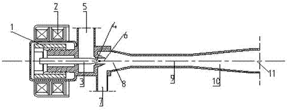
[0020] see figure 1 , A typical injector mainly includes five parts: nozzle 6, secondary flow inlet 7, suction chamber 8, mixing chamber 9 and diffuser section 10. After the high-temperature and high-pressure primary flow fluid at the inlet of the injector passes through the nozzle, the flow rate increases and the pressure decreases, creating a vacuum effect in the suction chamber to suck the secondary flow fluid. The primary flow is fully mixed, and the final mixed fluid passes through the diffuser section, where the velocity decreases and the pressure increases.

[0021] Please refer to figure 2 , the high-pressure superheated refrigerant vapor (primary flow fluid) in the ejector inlet section 5 passes through the main nozzle 6, and...


PUM


Abstract

A variable area ratio ejector based on an electronic expansion valve comprises an electric adjusting device, an inlet segment, a nozzle, a suction chamber, a mixing chamber and a diffusion segment. The electric adjusting device comprises a valve seat, a thread transmission mechanism, a rotor, a coil and a needle valve. The needle valve penetrates through the inlet segment to extend to the nozzle. The nozzle, the suction chamber and the mixing chamber are connected sequentially. The needle valve is arranged in the inlet segment. A valve rod is connected with the rotor. The coil is arranged outside the rotor. The needle valve extends to the inlet segment so as to adjust the cross section area of a nozzle throat and change the area ratio of the ejector. According to a specific operation process in a refrigeration system, when the adjusting device is closed completely, the needle valve is completely attached to the nozzle, and the flow quantity of primary flow is zero; and when the adjusting device is opened completely, the needle valve gets away from the nozzle completely, and the flow quantity of the primary flow is maximum. Adjustment of the flow quantity under the variable working condition is achieved through the adjusting device of the electronic expansion valve, throttling loss in the refrigeration can be fully recycled, and energy waste is reduced. The characteristic of the small size of the electronic expansion valve is utilized, implementation is easy, and installation is convenient.

Description

technical field [0001] The invention relates to a variable area ratio ejector based on an electronic expansion valve, which is applied in the technical field of refrigeration. Background technique [0002] Taking the application of the ejector in the field of refrigeration as an example, its working principle is to use the high-pressure superheated refrigerant vapor (primary flow fluid) to increase the flow rate and reduce the pressure after passing through the main nozzle, so as to generate a vacuum effect in the suction chamber and suck the superheated refrigerant from the evaporator. Steam (secondary flow fluid), the secondary flow fluid is accelerated by the injection nozzle and mixed with the primary flow fluid in the equal-section mixing chamber, and then passes through the diffusion section, the speed decreases and the pressure rises. Applying ejector technology to the field of refrigeration can use low-grade heat energy to achieve the purpose of refrigeration, which ...

Claims


Application Information

Patent Timeline
Patent Type & Authority Applications(China)
IPC IPC(8): B05B7/04B05B7/12F25B41/00F25B41/34
CPCF25B41/00B05B7/04B05B7/12F25B2341/0013
Inventor 严嘉温娜
Owner SOUTHWEAT UNIV OF SCI & TECH
Learn More