Eureka AIR delivers breakthrough ideas for toughest innovation challenges, trusted by R&D personnel around the world.

Wood processing machine tool

A technology for processing machine tools and wood. It is applied in the field of wood processing machine tools. It can solve the problems of small compaction, heavy board load, and easy deviation of boards, and achieves the effects of convenient maintenance, simple structure, and reduced manual wood advancement.

Inactive Publication Date: 2017-07-11
SUZHOU YASIKE PRECISION CNC CO LTD
View PDF8 Cites 3 Cited by
  • Summary
  • Abstract
  • Description
  • Claims
  • Application Information

AI Technical Summary

Problems solved by technology

The technical problem is that it is not suitable for brittle plates and high-density plates. When used for brittle plates, the upper and lower rollers have pressure differences at different positions on the plates, which may easily cause brittle plates to break; when used for high-density plates, due to the density of the plates Therefore, the plate load on the machine tool is heavy, and the pressure between the plate and the lower roller is large. When the plate is too long, the pressing effect of the upper roller on the plate is small, and the plate is easy to shift.
[0004] There is also a Chinese patent CN105643727A disclosing a wood processing device, including a load frame, two gantry frames are arranged on the load frame, and two support beams are symmetrically arranged between the two gantry frames, and two support beams are hinged with The connecting rod is fixed with a decelerating motor, the output shaft of the decelerating motor is vertically arranged, and a rubber ring is coaxially arranged on the output shaft of the decelerating motor, and the connecting rods on the two supporting beams are connected by the first spring, but Its resistance is large and energy consumption is large

Method used


Image

  • Wood processing machine tool
  • Wood processing machine tool

Examples


Embodiment Construction

[0018] In order to make the purpose and technical solutions of the embodiments of the present invention more clear, the technical solutions of the embodiments of the present invention will be clearly and completely described below in conjunction with the drawings of the embodiments of the present invention. Apparently, the described embodiments are some, not all, embodiments of the present invention. Based on the described embodiments of the present invention, all other embodiments obtained by persons of ordinary skill in the art without creative efforts shall fall within the protection scope of the present invention.

[0019] Those skilled in the art can understand that, unless otherwise defined, all terms (including technical terms and scientific terms) used herein have the same meaning as commonly understood by those of ordinary skill in the art to which this invention belongs. It should also be understood that terms such as those defined in commonly used dictionaries shoul...


PUM


Abstract

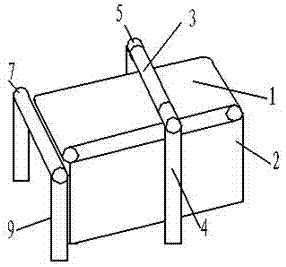
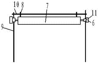
The invention belongs to the field of wood processing, in particular to a wood processing machine tool, comprising a transmission belt, a platform for installing and fixing the transmission belt, a wood limit structure, an auxiliary roller, an auxiliary roller mounting frame, and a motor; the auxiliary roller is installed on the auxiliary roller On the installation frame, it is located at the feeding end of the conveyor belt, and can be driven by the motor to rotate in line with the transmission direction of the conveyor belt; there are two wood limit structures, and the two wood limit structures are respectively installed on the auxiliary rollers The end of the installation frame; the wood limit structure includes a vertical baffle and a horizontal baffle. It can be applied to the smooth conveying and processing of various plates.

Description

technical field [0001] The invention belongs to the field of wood processing, in particular to a wood processing machine tool. Background technique [0002] Woodworking machine tool is a common processing equipment in woodworking equipment, which is widely used in the processing of furniture and decorative wood. When the sawing machine in the prior art processes wood, the operator needs to move the processed wood by hand and keep the processed wood moving smoothly, so as to facilitate the processing of the sawing machine. However, the work of moving and processing wood by hand not only has high work intensity, but also has high potential safety hazards in the process of pushing wood for processing, and also increases labor costs. [0003] In order to solve the potential safety hazards of hand pushing wood for processing, the existing technology such as Chinese patent CN104669367A provides a kind of wood processing machine tool, which includes: a machine frame, a press wheel...

Claims


Application Information

Patent Timeline
Patent Type & Authority Applications(China)
IPC IPC(8): B27B5/29B27B31/00
CPCB27B5/29B27B31/003B27B31/006
Inventor 马峻薛松
Owner SUZHOU YASIKE PRECISION CNC CO LTD
Why Eureka
Eureka Blog
Learn More