Plate clamper platform for falling weight impact test, and impact speed measurement method

A drop weight impact test and plate fixture technology, which is applied to devices using optical methods, measuring devices, analyzing materials, etc., can solve the difficulty of increasing the speed-time curve acquisition, affecting the measurement accuracy of the force sensor, and the complex calculation process. and other problems to achieve the effect of improving test reliability, improving measurement convenience, and improving measurement accuracy

Pending Publication Date: 2017-07-11
NANJING UNIV OF AERONAUTICS & ASTRONAUTICS
View PDF6 Cites 36 Cited by
  • Summary
  • Abstract
  • Description
  • Claims
  • Application Information

AI Technical Summary

Problems solved by technology

Since this method calculates the average speed and uses two sensors of light and force, the calculation accuracy is low and the calculation process is complicated
In addition, when performing an impact test with an angle, due to the influence of lateral force and friction caused by the angle, the measurement accuracy of the force sensor is seriously affected, and it is more difficult to obtain the speed-time change curve

Method used


Image

  • Plate clamper platform for falling weight impact test, and impact speed measurement method
  • Plate clamper platform for falling weight impact test, and impact speed measurement method
  • Plate clamper platform for falling weight impact test, and impact speed measurement method

Examples


Embodiment Construction

[0039] The present invention will be further described in detail below in conjunction with the accompanying drawings and specific preferred embodiments.

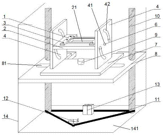
[0040] Such as figure 1 As shown, a plate fixture platform for drop weight impact test, including a fixture structure, a supporting lifting structure and a laser speed measuring device.

[0041] The fixture structure includes a plate clamping device, a multi-angle rotating device and a fixture bottom plate 7 .

[0042] The plate clamping device includes a clip 1 , a splint 2 and a splint fastening bolt 3 .

[0043] The thickness of the splint 2 is at least 20mm, and the recommended size is 25mm. There is a test piece impact groove 21 at the center of the splint 2. The test piece impact groove 21 is preferably a square groove with a depth of 150mm*100mm and a depth of 4mm.

[0044] The clips are arranged on the splints on both sides of the impact groove of the specimen, and the clips are detachably connected to the splints. ...


PUM


Abstract

The invention discloses a plate clamper platform for a falling weight impact test, and an impact speed measurement method. The plate clamper platform comprises a clamper structure, a supporting lifting structure and a laser sensor, wherein the clamper structure comprises a plate clamping device, a multi-angle rotation device and a clamper bottom plate, the multi-angle rotation device comprises wall plates, wall plate bolts and a bottom plate bolt, each wall plate is provided with a central hole and two arc-shaped grooves, the two arc-shaped grooves are symmetrically arranged relative to the central hole, clamping plates can rotate along the arc-shaped grooves after the wall plate bolts are completely loosened, the supporting lifting structure comprises a platform and a lifting driving device, the clamper bottom plate can rotate by adopting the bottom plate bolt as the center and can slidably move along a straight strip hole, and the laser sensor is arranged below the weight tray positioned on the periphery of a hammer head. With the plate clamper platform and the impact speed measurement method of the present invention, the composite material plate specimen can be tightly clamped, the multi-angle impact on the specimen can be achieved, and the speed change during the drop hammer falling and impact process can be real-timely measured.

Description

technical field [0001] The invention relates to the field of material mechanical performance testing, in particular to a plate fixture platform for a drop weight impact test and a method for measuring impact velocity. Background technique [0002] At present, in the process of testing the mechanical properties of composite materials, it is essential to test the impact resistance of composite materials. In order to test and evaluate the impact resistance of composite materials, it is generally necessary to perform drop weight impact tests on composite plate test pieces. In the drop weight impact test, it is required to realize the fixed clamping of the plate test piece, and to collect the speed-time change curve during the drop process of the drop weight and the impact process. [0003] In the existing general drop-weight impact test of composite material plates, the drop weight in the drop-weight impact device falls vertically, and impacts the center of the specimen clamped...

Claims


Application Information

Patent Timeline
Patent Type & Authority Applications(China)
IPC IPC(8): G01N3/303G01N3/04G01P3/36
CPCG01N3/04G01N3/303G01P3/36G01N2203/0039G01N2203/04
Inventor 陆晓华徐瑀童左洪福邵传金
Owner NANJING UNIV OF AERONAUTICS & ASTRONAUTICS
Why Eureka
Try Eureka