

Powerful mixer control method and system
A powerful mixer and control method technology, applied in the direction of control/adjustment system, mechanical oscillation control, non-electric variable control, etc., can solve the problems of shortening the service life of key equipment and affecting the normal use of powerful mixers, and avoid resonance phenomenon , the effect of protecting from damage
- Summary
- Abstract
- Description
- Claims
- Application Information
AI Technical Summary
Problems solved by technology
Method used
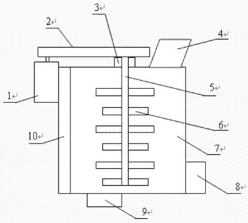
Image

Examples
Embodiment 1
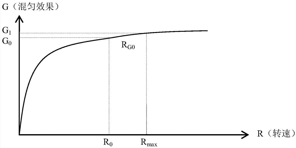
[0058] First introduce the working principle that the present invention is based on, see figure 2 , which is a graph showing the relationship between the mixing effect of the intensive mixer provided by the present invention and the rotational speed of the stirring paddle.
[0059] Among them, the abscissa R is the rotation speed of the stirring paddle, and the ordinate G is the mixing effect.
[0060] It can be understood that the stirring paddle is driven to rotate by the paddle motor. The rotational speed of the stirring paddle motor is controlled by the stirring paddle inverter. When the output frequency of the stirring paddle inverter is different, the corresponding rotating speed of the stirring paddle motor is different. When the output frequency of the stirring paddle inverter is higher, the corresponding speed of the stirring paddle motor is higher, that is, the speed of the stirring paddle is also higher.
[0061] From figure 2 It can be seen that the mixing effec...
Embodiment 2
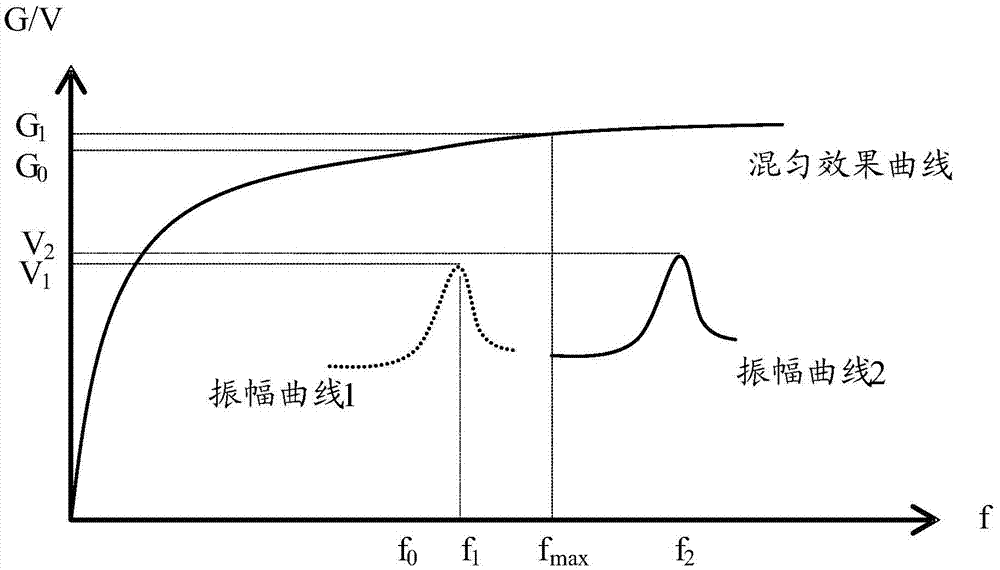
[0089] see Figure 5 , which is a flow chart of Embodiment 2 of the control method provided by the present invention.
[0090] Detecting the amplitude of the intensive mixer within the working frequency range of the agitator frequency converter, specifically including S501 and S502;
[0091] S501: Control the operating frequency of the agitating paddle frequency converter to increase successively with predetermined frequency steps within the operating frequency range;
[0092] For example, f=N i , N i+1 =N i +N, where N i It is the output frequency of the frequency converter of the stirring paddle that needs to detect the amplitude of the intensive mixer. N is the predetermined frequency step size, N i The value range of is the working frequency range ((N min ,N max ) within the frequency.
[0093] It should be noted that the value of N can be set according to actual needs, for example, it can be set to 1, that is, the value of N is incremented with 1 Hz as the predet...
PUM
 Abstract
Description
Claims
Application Information