Three-finger-three-knuckle under-actuated mechanical arm with finger tail end path being controllable

An underactuated and manipulator technology, which is applied in the direction of program-controlled manipulators, manipulators, chucks, etc., can solve the problems of uncertain movement of finger end trajectory, loss of finger flexibility, etc., achieve convenient and fast disassembly and installation, improve grasping flexibility, and structure and the effect of simple principle

Active Publication Date: 2017-07-14
HARBIN INST OF TECH
View PDF3 Cites 16 Cited by
  • Summary
  • Abstract
  • Description
  • Claims
  • Application Information

AI Technical Summary

Problems solved by technology

[0004] The purpose of the present invention is to solve the problem that the existing underactuated manipulator loses the necessary finger flexi

Method used


Image

  • Three-finger-three-knuckle under-actuated mechanical arm with finger tail end path being controllable
  • Three-finger-three-knuckle under-actuated mechanical arm with finger tail end path being controllable
  • Three-finger-three-knuckle under-actuated mechanical arm with finger tail end path being controllable

Examples


specific Embodiment approach 1

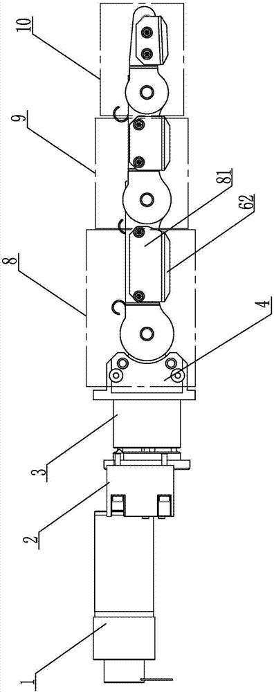
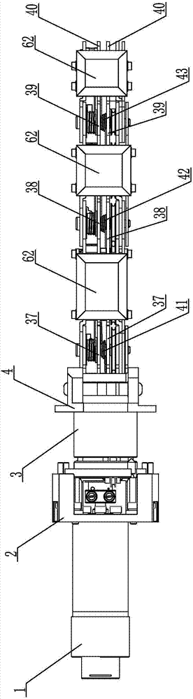
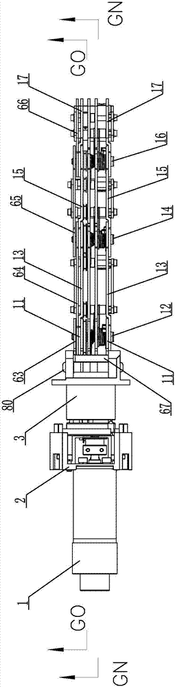
[0044] Specific implementation mode one: combine Figure 1 to Figure 16 Describe this embodiment. This embodiment includes three underactuated fingers, an underactuated manipulator base 70, a finger rotating motor 71, a driving gear 72, a first driven gear 73, and a second driven gear 74. The three underactuated fingers form a triangular row. cloth, each underactuated finger includes a power drive part and a joint part, the joint part is connected to the output end of the power drive part, and the joint part includes a first joint 8, a second joint 9, a third joint 10, a guide wheel mechanism, a reset Mechanism and locking mechanism, the first joint 8, the second joint 9 and the third joint 10 are rotatably connected in turn, and the guide wheel mechanism, reset mechanism and locking mechanism are installed on the first joint 8, the second joint 9 and the third joint On the joint 10, the guide wheel mechanism is driven by the power drive part to realize the grasping action of ...

specific Embodiment approach 2

[0049] Specific implementation mode two: combination Figure 9 , Figure 11 and Figure 14 Describe this embodiment. This embodiment also includes a plurality of bearings 75 and a cover body 76. The plurality of bearings 75 are respectively set on the fixed sleeve 3 at the upper end of the first driven gear 73 and the second driven gear 74. The cover body 76 covers On the entire powered portion of the underactuated manipulator base 70 outside. With such arrangement, it is convenient to ensure that two adjacent fingers rotate smoothly in the same or opposite direction. Other compositions and connections are the same as in the first embodiment.

[0050] When the motor 1 has no output, the underactuated mechanical finger will return to the initial state under the action of the joint return spring and the mechanical limit (at this time, the entire finger is in a horizontal state, and the other components are the motor 1, the connecting sleeve 2, and the fixing sleeve 3 and fin...

specific Embodiment approach 3

[0051] Specific implementation mode three: combination Figure 5 Describe this embodiment, the power drive part of this embodiment also includes tightening wheel cover 18 and idler bracket 19, tightening wheel cover 18 is installed in the connecting sleeve 2 and is sleeved on the output shaft of motor 1, and idler bracket 19 Installed on the connecting sleeve 2, the second guide wheel 17 partially extends into the fixed sleeve 3, and the first guide wheel 6 and the second guide wheel 7 are all installed on the guide wheel bracket 19. In this way, the tightening wheel cover 18 and the winding wheel are fixed on the output shaft of the motor through screws, the motor is fixed on the connecting sleeve through screws, the guide wheel bracket is fixed on the connecting sleeve through screws, and the connecting sleeve is connected through screws. This part is integrally fixed on the base, so that the connection between the motor and other components is more compact. Other compositi...


PUM


Abstract

The invention relates to a modular under-actuated mechanical arm, in particular to a three-finger-three-knuckle under-actuated mechanical arm with a finger tail end path being controllable. The three-finger-three-knuckle under-actuated mechanical arm with the finger tail end path being controllable is used for solving the problem that because of the coupling of the joint movement of an under-actuated mechanical arm, the finger tail end path is not certain during movement, and then an existing under-actuated mechanical arm loses necessary finger flexibility. A finger rotation motor (71) is installed in the middle of three under-actuated fingers which are triangularly arranged. A drive gear (72) is installed on an output shaft of the finger rotation motor (71). A first driven gear (73) and a second driven gear (74) are arranged on connection sleeves (2) of two adjacent under-actuated fingers, the drive gear (72) is meshed with the first driven gear (73), and the first driven gear (73) is meshed with the second driven gear (74). The three under-actuated drive fingers are installed on an under-actuated mechanical arm base (70). The three-finger-three-knuckle under-actuated mechanical arm with the finger tail end path being controllable is used as a tail end execution mechanical arm of an intelligent robot.

Description

technical field [0001] The invention relates to an underactuated manipulator, in particular to a three-finger-three-knuckle underactuated manipulator with controllable trajectory of finger ends. Background technique [0002] As an important interface for intelligent robots to interact with the surrounding environment, the importance of the manipulator is self-evident. In mobile robots, especially those powered by a power supply, reducing energy consumption is an indicator that needs special consideration. Therefore, underactuated manipulators with fewer drive units and less energy consumption have become the first choice for mobile robots. However, unlike the motion and grasping force of each joint of a fully-actuated manipulator, which is completely determined by the drive unit, the motion of each joint of an under-actuated manipulator is also affected by the mechanical structure and external contact, which makes the motion of its fingers have a strong kinematic coupling. ...

Claims


Application Information

Patent Timeline
IPC IPC(8): B25J15/10B25J9/12
CPCB25J9/126B25J15/10
Inventor 王伟东赵思宇杜志江
Owner HARBIN INST OF TECH
Why Eureka
Try Eureka