Fault diagnosis method of transformer lightning Impulse based on big data

A lightning shock and transformer technology, applied in the direction of testing the dielectric strength, etc., can solve the problems of consuming a lot of time, manpower and material resources, unable to determine the location of the fault in the transformer, and unable to reflect the fault time

Active Publication Date: 2017-07-14
CHINA THREE GORGES UNIV
View PDF5 Cites 7 Cited by
  • Summary
  • Abstract
  • Description
  • Claims
  • Application Information

AI Technical Summary

Problems solved by technology

For small faults, it is difficult to judge by the head-end voltage and neutral point current method. At this time, it is necessary to perform fast Fourier transformation on the voltage and current time-domain waveforms to obtain their respective spectra, and then divide the spectrum of the current signal by the voltage The transfer function value is obtained from the frequency spectrum of the signal, and minor faults can be judged through the transfer function waveform, but the transfer function is frequency-dependent, which cannot reflect the fault time, nor can it determine the location of the fault in the transformer
After confirming that there is a fault in the transformer, fault diagnosis methods such as ultra-high frequency partial discharge signals or ultrasonic partial discharge can be used to locate the fault. Small, if the approximate scope of the fault cannot be determined, it will take a lot of time, manpower and material resources to locate the fault after multiple investigations

Method used


Image

  • Fault diagnosis method of transformer lightning Impulse based on big data
  • Fault diagnosis method of transformer lightning Impulse based on big data
  • Fault diagnosis method of transformer lightning Impulse based on big data

Examples


Embodiment Construction

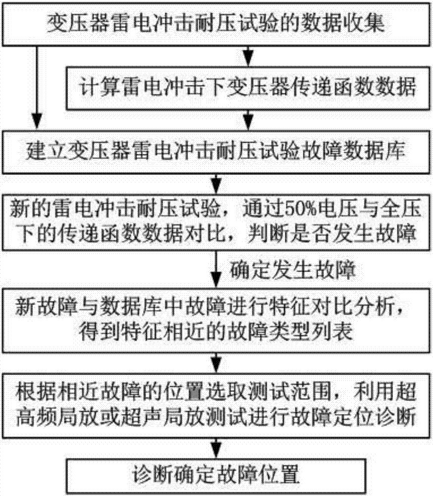
[0018] Such as figure 1 As shown, a fault diagnosis method for transformer lightning impulse based on big data includes the following steps:

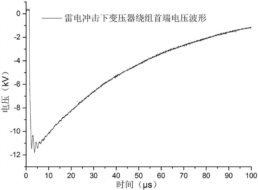
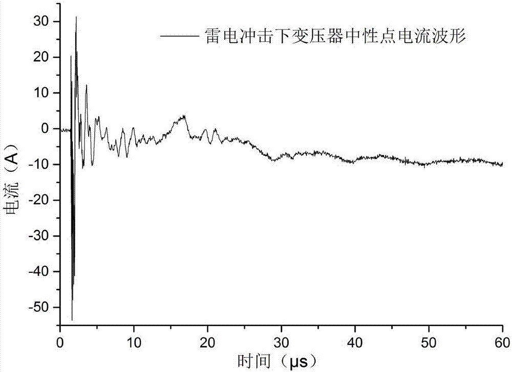
[0019] Step 1): Collect the historical data of the transformer lightning impulse withstand voltage test. For example, the sampling frequency of the head-end voltage and neutral point current data in the test is 100MHz, and the number of data sampling points recorded for 200μs is 20,000 points, and the lightning is drawn according to the data of the sampling points The voltage waveform at the head end of the transformer winding under the impact is as follows: figure 1 , draw the neutral point current waveform as figure 2 . According to formula 1, fast Fourier transform is performed on the head-end voltage data and neutral point current data measured by the test respectively, where x(n) is discrete signal data, such as voltage or current sampling data, and X(k) is Fast Fourier transform data of the signal, is the kernel function of ...


PUM


Abstract

Provided is a fault diagnosis method of transformer thunder impacts based on big data. The method comprises steps of collecting historical data of a transformer thunder impact voltage withstanding test and carrying out rapid Fourier transform on head end voltage data and neutral point current data measured in the test; establishing a fault standard database, and carrying out standardization processing so as to obtain transfer function data; carrying out standardization processing on the new thunder impact voltage withstanding test data to obtain transfer function data, and by comparing the transfer function data under 50% thunder impact voltage and under full voltage, judging whether a failure occurs; selecting related data of the same type of transformers in a fault database, and solving a correlation index rho between the transfer function data of the new test and the transfer function data in the fault database; and selecting the proximal fault information according to sequenced fault lists, setting a deviation value eta% and by taking a fault corresponding position as a center, selecting a winding segment of the eta% of the total turn number to be a test range for carrying out fault positioning diagnosis. According to the invention, feature classification is performed on massive data with fault waveforms, so the rough range of the faults can be determined; fault positioning time can be greatly reduced; and fault diagnosis is allowed to be quite quick and effective.

Description

technical field [0001] The invention relates to a large data-based fault diagnosis method for transformer lightning impact, and relates to the field of transformer fault detection. Background technique [0002] Before the transformer leaves the factory, it is necessary to carry out the assessment of the lightning impulse withstand voltage test. The fault diagnosis of the lightning impulse test is mostly used by the neutral point current method and the transfer function method. It mainly compares the test data under 50% voltage and full voltage. For small faults, it is difficult to judge by the head-end voltage and neutral point current method. At this time, it is necessary to perform fast Fourier transform on the voltage and current time-domain waveforms to obtain their respective spectra, and then divide the spectrum of the current signal by the voltage The transfer function value is obtained from the frequency spectrum of the signal, and small faults can be judged through...

Claims


Application Information

Patent Timeline
Patent Type & Authority Applications(China)
IPC IPC(8): G01R31/12
CPCG01R31/12
Inventor 普子恒方春华吴田黎鹏张宇娇
Owner CHINA THREE GORGES UNIV
Why Eureka
Try Eureka