
Simulation test device of electric pile cathode of air supply system of fuel cell

An air supply and fuel cell technology, applied in the direction of measuring devices, measuring electricity, measuring electrical variables, etc., can solve the problem of not providing equipment, not being able to quickly design an air supply auxiliary system, and the parameters of key components cannot be well matched, etc. problems, to achieve the effect of improving development efficiency and speeding up the matching testing process

Inactive Publication Date: 2017-07-14
TONGJI UNIV
View PDF11 Cites 15 Cited by
  • Summary
  • Abstract
  • Description
  • Claims
  • Application Information

AI Technical Summary

Problems solved by technology

[0008] The above-mentioned disclosed technology only provides different specific solutions for the design of fuel cell air supply auxiliary systems, but does not provide the development process, development method and equipment used in the development process. When designing the air supply subsystem, you will face the following Problems: (1) A good air supply auxiliary system cannot be quickly designed based on the characteristic parameters of the existing stack without real objects; (2) The key component parameters in the air supply auxiliary system cannot be well matched

Method used


Image

  • Simulation test device of electric pile cathode of air supply system of fuel cell
  • Simulation test device of electric pile cathode of air supply system of fuel cell
  • Simulation test device of electric pile cathode of air supply system of fuel cell

Examples


Embodiment 1

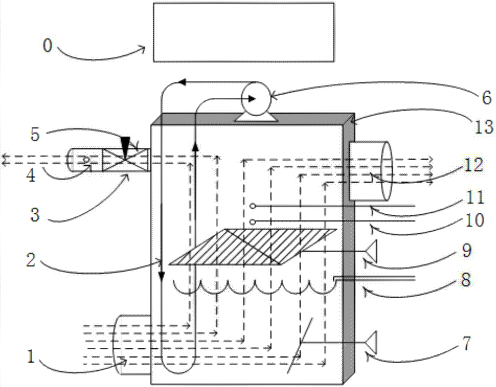
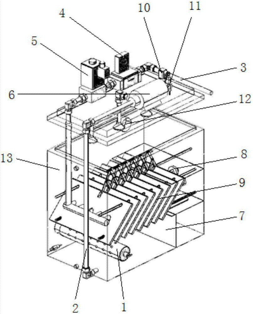
[0034] A stack cathode simulation test device for fuel cell air supply system, refer to figure 1 , figure 2 , including a housing 13, a circulating water circuit 2 for installing an electric water pump 6, an air intake pipe 1 for simulating the air intake of the stack, an air discharge port 12 for discharging excess air, and a cathode volume adjustment chamber 7 for adjusting the volume of air flowing through 1. A flow resistance regulator 9 for adjusting the pressure loss of air flowing through and an air consumption port 3 for simulating oxygen consumption. The front end of the air consumption port 3 is sequentially installed with an electric valve 5 and a flow sensor 4 connected to the control computer 0 . The air intake pipe 1 and the cathode volume adjustment chamber 7 are arranged at the bottom of the casing 13, the air discharge port 12 is arranged at the top of the casing 13, the flow resistance regulator 9 is arranged at the top of the cathode volume adjustment chamb...


PUM


Abstract

The invention relates to a simulation test device of an electric pile cathode of an air supply system of a fuel cell. The simulation test device comprises a housing body, an air inlet pipe, an air discharging opening, a circulation water path, a cathode volume adjusting cavity, flow resistance adjusters and an air consumption opening. The air inlet pipe and the cathode volume adjusting cavity are arranged under the housing body. The air discharging opening is arranged in the upper part of the housing body. The flow resistance adjusters are arranged in the upper part of the cathode volume adjusting cavity. A heating piece is arranged between the flow resistance adjusters. A spraying mechanism is arranged on the upper part of the circulation water path. Compared with the prior art, the simulation test device is characterized in that simulation is performed according to the static state volume, the air flow resistance, and the oxygen consumption rules and principles of the known fuel cell electric pile; rapid configuration is performed through known parameters of the fuel cell; the simulation test device is used for replacing a true electric pile in a fuel cell system matched development process; a matched test process is accelerated; and system development efficiency is improved.

Description

technical field [0001] The invention belongs to the technical field of fuel cells, and in particular relates to a simulation test device for stack cathodes of an air supply system of a fuel cell. Background technique [0002] Fuel cells generate electricity directly through the electrochemical reaction of fuel (such as hydrogen). Because fuel cells have a series of excellent performances such as high efficiency, zero emissions, stable operation, and no noise, they are regarded as the most likely power source for future automobiles. Fuel cell vehicles are the development trend of the future automobile industry. Fuel cells use electrochemical reactions to convert chemical energy into electrical energy, and are not limited by the Carnot cycle. The theoretical efficiency can reach up to 80%. Due to the influence of activation polarization, ohmic polarization and the diffusion effect of strong tea inside the battery during the chemical reaction, the power generation efficiency i...

Claims


Application Information

Patent Timeline
IPC IPC(8): G01R31/36
CPCG01R31/385
Inventor 张新丰姚川棋罗明慧许思传章桐
Owner TONGJI UNIV
Learn More