
Ground effect flyer

A ground-effect aircraft and a technology for an aircraft, applied in the field of aircraft, can solve the problems of slow sailing speed, poor ride comfort, low sailing speed, etc., and achieve the effects of reducing drag and increasing flight lift.

Active Publication Date: 2007-06-06
中国科技开发院有限公司
View PDF1 Cites 6 Cited by
  • Summary
  • Abstract
  • Description
  • Claims
  • Application Information

AI Technical Summary

Problems solved by technology

[0010] (1) The speed of navigation is slow, which is not conducive to improving the efficiency of maritime transportation
[0011] (2) Affected by the ups and downs of sea wind and waves, the ride comfort is poor
[0012] (3) It is necessary to build a wharf with a large draft and corresponding facilities, and the seaworthiness is not good
[0013] 3. Existing small-scale ground-effect aircraft, such as the disclosed small-scale ground-effect aircraft of Chinese Patent Application No. 02115191.1, has a small tonnage and scale (5 tons, a wingspan of 9.8 meters, and a total length of 16 meters), and a low speed (150 km / h ), small passenger capacity (only more than ten people), low wind and wave resistance (the height of take-off and landing waves does not exceed 1 meter, and the cruise flight height does not exceed 1.5 meters). Generally, it can only be used in inland rivers and lakes.

Method used


Image

  • Ground effect flyer
  • Ground effect flyer
  • Ground effect flyer

Examples


Embodiment Construction

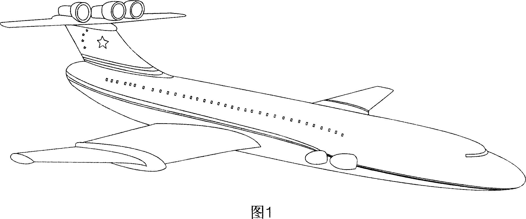
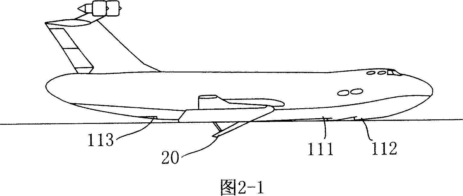
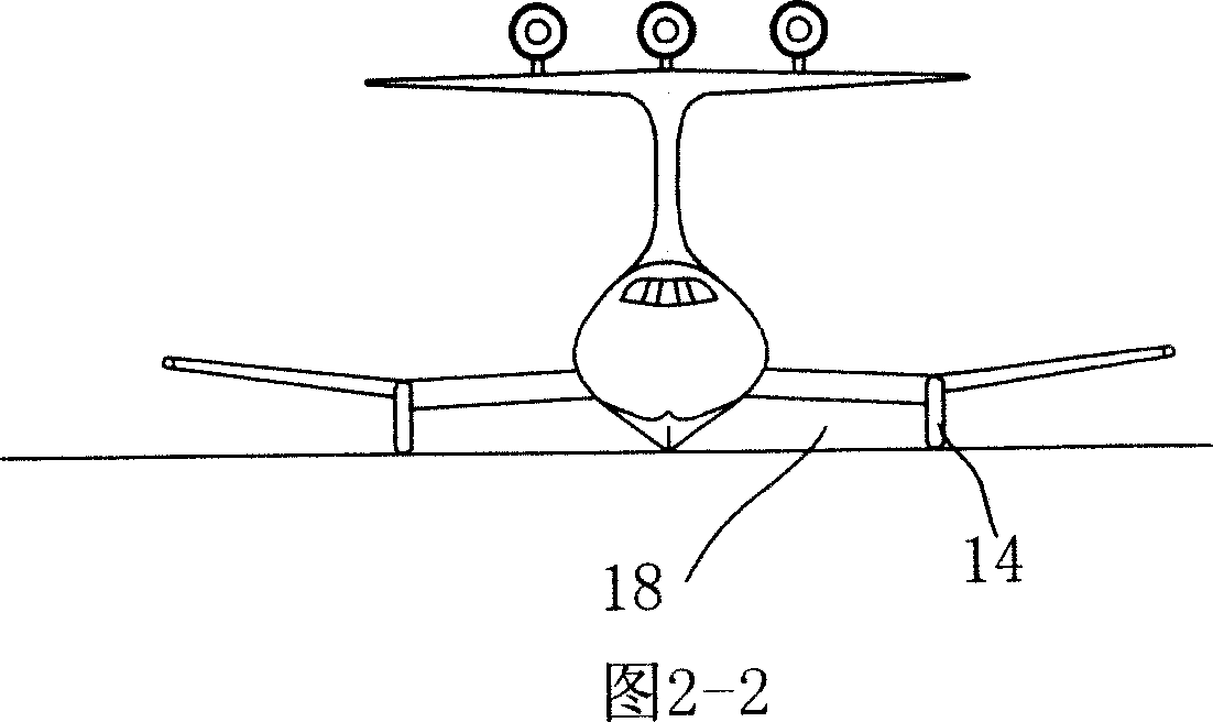
[0039] The present invention as shown in Fig. 1 Fig. 2 Fig. 3 comprises fuselage middle section 2, main wing 6, take-off engine 12 and nozzle thereof. The middle section of the fuselage 2, the main wing 6, the partition plate 14, and the flap 4 on the downward deflection of the trailing edge of the wing form a closed air chamber 18 for increasing lift. The jet flow of the take-off engine is introduced into the booster air cavity 18, and the air flow is blocked in the cavity, and the kinetic energy is converted into pressure energy, and the additional pressure acting on the lower surface of the main wing 6 produces additional cushioning lift. The pad lift can lift the aircraft, reducing the area where the aircraft is in contact with water, thereby reducing the sliding resistance of the aircraft. Above-mentioned air cavity 18 of increasing lift is the cavity that is made up of 2 bottoms of fuselage middle section, main wing 6 lower aerofoils, dividing plate 14 below main wing 6 ...


PUM


Abstract

The present invention discloses one kind of large ground effect flyer flying in the ground effect flying region. The large ground effect flyer includes a fuselage, wings and engines. It has cruising engine in the tail, thrusters in the nosing and wings, and lift boosting air cavities below wings. The present invention leads the jet flow of the thrusters to the lift boosting air cavities with the turning jets and converts airflow kinetic energy into pressure energy to generate great lift. It has cruising engine in the tail and elevators with trimmers to ensure the reasonable matching between the attack angle focus and the height focus and the balancing of the elevator force in long term flying, so as to realize the balancing and maneuvering in the longitudinal plane and to ensure the stable flying of the flyer in the air near water surface.

Description

technical field [0001] The invention relates to an aircraft, in particular to a large-scale high-speed ground-effect aircraft with high-efficiency power-up effect and flying in a ground-effect flight area. Background technique [0002] High-efficiency power-lift ground-effect aircraft is a high-speed transportation tool. When the aircraft flies close to the ground or water surface, the air flows through the narrow passage between the wing and the ground or water surface to generate additional power-lift effect. The height at which the ground lift effect exists is called the ground effect zone, and its height is approximately equivalent to the length of the wingspan. The closer to the ground, the stronger the ground effect. The ground effect aircraft is a new type of transportation tool developed by using the aerodynamic ground effect principle to fly over the ground or over the sea. Because the ground-effect aircraft has the same high speed as an airplane, although it can ...

Claims


Application Information

Patent Timeline
Patent Type & Authority Applications(China)
IPC IPC(8): B64C35/00B64C1/00B64C3/00B64C5/00
Inventor 李绪鄂伏·赫·基里诺维赫顾诵芬崔尔杰格·波·库兹涅佐夫罗家枢伏·赫·布洛欣宋明德陈洪若阿·依·普里瓦洛夫褚林堂勃·马·拉里兹赫李洪畴韩光维李先达
Owner 中国科技开发院有限公司
Learn More