Terminal and antenna structure thereof

An antenna structure and terminal technology, applied in the field of communication, to achieve the effect of optimizing radiation performance and improving aesthetics

Inactive Publication Date: 2017-07-14
NUBIA TECHNOLOGY CO LTD
View PDF4 Cites 9 Cited by
  • Summary
  • Abstract
  • Description
  • Claims
  • Application Information

AI Technical Summary

Problems solved by technology

[0004] In recent years, with the rapid development of mobile terminals and smart phones, smart phones have entered the era of all-metal industrial desig

Method used


Image

  • Terminal and antenna structure thereof
  • Terminal and antenna structure thereof
  • Terminal and antenna structure thereof

Examples


Embodiment 1

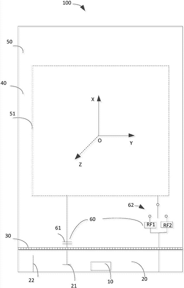
[0084] Such as image 3 As shown, the antenna structure 100 provided by the embodiment of the present invention is suitable for a terminal with a metal casing (that is, the above-mentioned mobile terminal), image 3 The OXY plane of the XYZ coordinate system can be understood as the surface where the terminal screen is located, or the plane where the terminal metal backplane is located, and the Z axis is perpendicular to the XY plane. image 3 The XYZ coordinate system in the following embodiments and other drawings are the same as the XYZ coordinate system in the terminal reference coordinate system. The antenna structure 100 includes an antenna radiation area 20 and a USB interface coupled with the antenna radiation area 20. In some embodiments, the USB interface may be a USB2.0, USB3.0 or a USB-C interface. image 3 The USB-C interface 10 is taken as an example for description. The antenna radiation area 20 is to separate the metal shell 40 of the terminal through the mic...

Embodiment approach 1

[0098]Turn off the SPDT switch 62, and the adjustable capacitor 31 is loaded with 4.7PF. At this time, the feed point 21 is coupled and fed, and the antenna will generate a low frequency resonance (880-960MHz), an intermediate frequency resonance (1710-1880MHz), and a Ultra-high frequency resonance (2300-2500MHz). The low-frequency resonance and intermediate-frequency resonance are generated by the body resonance of the planar inverted antenna PIFA (Planar Inverted-FAntenna), and the ultra-high frequency is generated by the low-frequency triple frequency and the coupling of the USB-C interface 10 and the antenna radiation area 10 .

Embodiment approach 2

[0100] Disconnect the SPDT switch 62, by changing the value of the adjustable capacitor 31, the pulling of the intermediate frequency resonance is realized, and 1.8PF and 1.2PF are loaded respectively, so that the intermediate frequency resonance shifts to the high frequency, covering the frequency bands of 1850-1990MHz and 1920-2170MHz respectively .


PUM

PropertyMeasurementUnit
Widthaaaaaaaaaa

Abstract

The invention discloses a terminal and an antenna structure thereof, and a special protection sleeve. The antenna structure is applicable to the terminal with a metal shell; the antenna structure comprises an antenna radiation region and a USB-C interface coupled with the antenna radiation region; the antenna radiation region separates the metal shell of the terminal through a micro slit; the antenna radiation region is connected with a regulation apparatus for regulating the resonant frequency of the antenna structure; the antenna radiation region is provided with multiple feed points; coupled feeding is performed, and the resonant frequency of the antenna structure is regulated by adopting the regulation apparatus to obtain different frequency band combinations, so as to realize domestic all-network-band coverage of the antenna structure; radio frequency signals and grounding signals can be switched to different feed points via selector switches by the multiple feed points so as to obtain different resonant frequencies; and equivalently, switching of virtual antennas is performed, and the current path of the antenna structure is changed, so that balance of the antenna performance under holding of left and right hands can be realized successfully.

Description

[0001] 【Technical field】 [0002] The present invention relates to the technical field of communication, in particular to a terminal and its antenna structure. [0003] 【Background technique】 [0004] In recent years, with the rapid development of mobile terminals and smart phones, smart phones have entered the era of all-metal industrial design. The complex electromagnetic environment and limited space of all-metal structures have brought great challenges to the design of mobile phone antennas. At present, the metal structure of the whole metal machine, the environment of the headroom of the antenna is getting smaller and smaller, and there are many devices placed around the headroom, etc., making it more and more difficult for the antenna performance of the all-metal shell mobile phone to achieve broadband and high radiation efficiency. The market has a wide demand for the broadband and performance of mobile phone antennas for domestic full Netcom and overseas frequency band ...

Claims


Application Information

Patent Timeline
IPC IPC(8): H01Q1/24H01Q1/44H01Q1/50H01Q3/00H01Q5/10
CPCH01Q1/241H01Q1/44H01Q1/50H01Q3/00H01Q5/10
Inventor 马坤
Owner NUBIA TECHNOLOGY CO LTD
Why Eureka
Try Eureka