Supercharge Your Innovation With Domain-Expert AI Agents!

Connecting rod of transverse stabilization rod and machining process of ball pin assembly

A technology of horizontal stabilizer bar and processing technology, which is applied to the interconnection system, cantilever mounted on the pivot, suspension, etc., which can solve the problems of low processing production efficiency, large blank machining allowance, and reduced service life of connecting rods , to achieve the effect of increasing processing efficiency, reducing processing cost, and good working properties

Inactive Publication Date: 2017-07-18
BAODING GREAT MACHINERY CO LTD
View PDF4 Cites 7 Cited by
  • Summary
  • Abstract
  • Description
  • Claims
  • Application Information

AI Technical Summary

Problems solved by technology

[0003] The end of the ball pin has a cross-section because it is difficult to achieve a complete spherical shape by machining, so that the contact area between the ball pin and the bush becomes smaller due to the cross-section during the swing of the ball pin in the bush, the wear of the bush is accelerated, and the connecting rod Reduced service life
In addition, there are many processes and complex mold structure in the cold heading process of the ball pin blank; in the ball pin turning process, due to the complex structure and the large machining allowance of the blank, two turnings (rough turning and fine turning) are required to complete the processing and production efficiency. Low cost, much waste of raw materials; it is not easy to ensure the roundness of the two poles when the ball end of the ball pin is machined, the roughness is not easy to guarantee during the rolling process of the ball pin, and the rolling pressure is not easy to adjust, and the rolling wheel is easy to damage

Method used


Image

  • Connecting rod of transverse stabilization rod and machining process of ball pin assembly
  • Connecting rod of transverse stabilization rod and machining process of ball pin assembly
  • Connecting rod of transverse stabilization rod and machining process of ball pin assembly

Examples


Embodiment Construction

[0029] It should be noted that, in the case of no conflict, the embodiments of the present invention and the features in the embodiments can be combined with each other.

[0030] The present invention will be described in detail below with reference to the accompanying drawings and examples.

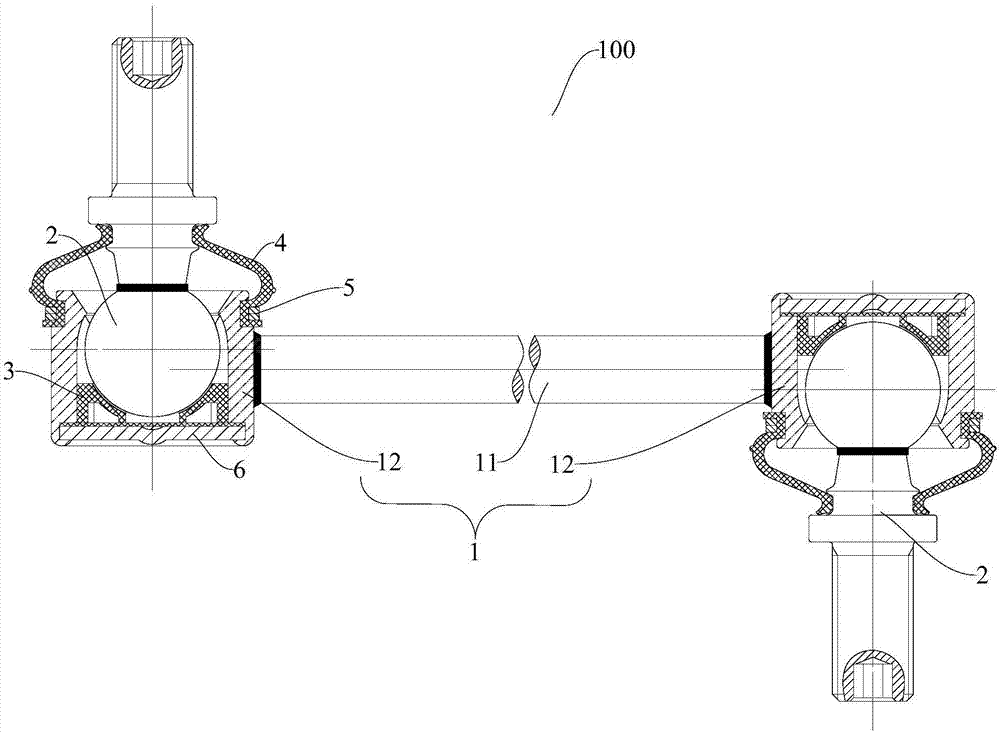
[0031] The connecting rods 100 of the stabilizer bar are used to fix the stabilizer rod on the left and right suspension lower arms or the shock absorber struts, and for four-wheeled vehicles, each vehicle is provided with four connecting rods 100 .

[0032] like Figure 1-Figure 2 As shown, the connecting rod 100 of the stabilizer bar includes a ball pin seat assembly 1 , a bush 3 and a ball pin assembly 2 .

[0033] Wherein, the ball pin seat assembly 1 has an intermediate connecting rod 11 and a ball pin seat 12, and the ball pin seat 12 is fixedly connected with the intermediate connecting rod 11. For example, the ball pin seat 12 can be connected with the intermediate connecting ro...


PUM


Abstract

The invention discloses a processing technology of a connecting rod of a horizontal stabilizer bar and a ball pin assembly. The connecting rod of the horizontal stabilizer bar includes: a ball pin seat assembly, and the ball pin seat assembly has an intermediate connecting rod and a ball pin assembly. Pin seat; bushing, the bushing is installed in the ball pin seat and has a spherical installation cavity; ball pin assembly, the ball pin assembly includes a ball pin and a ball pin rod, the ball pin and the ball pin The ball pin rod is fixedly connected and hinged to the installation cavity, and the end of the ball pin away from the ball pin rod is a spherical surface. The connecting rod of the stabilizer bar according to the embodiment of the present invention can keep the contact area between the ball pin and the bushing unchanged by arranging a spherical ball pin to prevent the bushing from being worn out. The moment of the connecting rod is stable during the swing process and the working performance good.

Description

technical field [0001] The invention relates to a processing technology of a connecting rod of a lateral stabilizer bar and a ball pin assembly. Background technique [0002] When the vehicle is driving on an uneven road in a straight line or when turning, the wheels on the left and right sides are at different heights, and the vehicle body will roll laterally. . The stabilizer bar is fixed on the left and right hanging lower brackets or shock absorber struts through connecting rods, and the connecting rods are mostly assembled through the ball pin structure. In the related technology, the processing technology of the ball pin assembly is: raw material, cold heading, rolling Silk, turning (rough turning, fine turning), tumbling, cleaning. [0003] The end of the ball pin has a cross-section because it is difficult to achieve a complete spherical shape by machining, so that the contact area between the ball pin and the bush becomes smaller due to the cross-section during th...

Claims


Application Information

Patent Timeline
IPC IPC(8): B60G21/055B60G7/00B23P15/00
CPCB60G21/0551B23P15/00B60G7/005B60G2202/135
Inventor 李海兴王学升石炳雨宗刘冬熊雪娇
Owner BAODING GREAT MACHINERY CO LTD
Features
  • R&D
  • Intellectual Property
  • Life Sciences
  • Materials
  • Tech Scout
  • Unparalleled Data Quality
  • Higher Quality Content
  • 60% Fewer Hallucinations
Learn More