
Automatic adjustment vibration reducer

An automatic adjustment and shock absorber technology, which is applied in the direction of shock absorber, liquid shock absorber, shock absorber-spring combination, etc., can solve the problems of unable to adjust the main piston and limited vibration damping effect, and achieve good vibration damping effect , Improve the effect of resistance and quick damping function

Active Publication Date: 2017-07-18
TAIZHOU VOCATIONAL & TECHN COLLEGE
View PDF7 Cites 12 Cited by
  • Summary
  • Abstract
  • Description
  • Claims
  • Application Information

AI Technical Summary

Problems solved by technology

[0004] The disadvantage of the above-mentioned shock absorber is that it cannot adjust the resistance of the main piston according to the vibration amplitude, so the damping effect is limited

Method used


Image

  • Automatic adjustment vibration reducer
  • Automatic adjustment vibration reducer
  • Automatic adjustment vibration reducer

Examples


Embodiment Construction

[0025] The following are specific embodiments of the present invention and in conjunction with the accompanying drawings, the technical solutions of the present invention are further described, but the present invention is not limited to these embodiments.

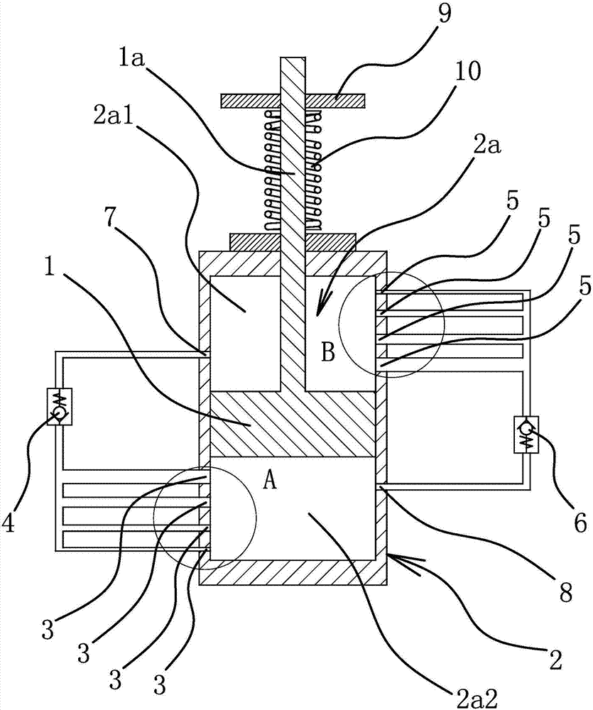
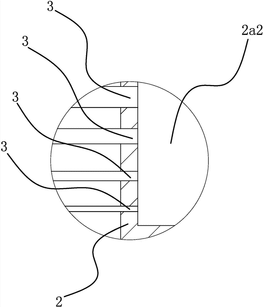
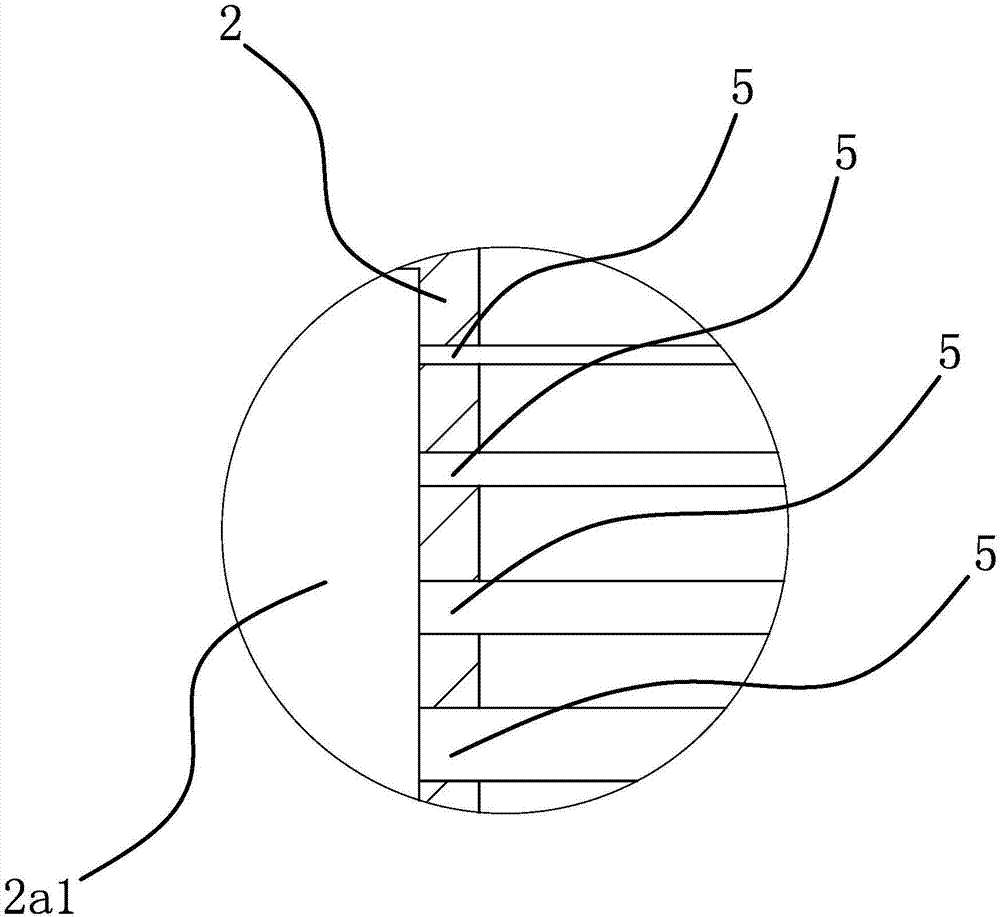
[0026] like figure 1As shown, the self-adjusting shock absorber includes a main piston 1, a piston rod 1a and a hydraulic cylinder 2, the hydraulic cylinder 2 has a working oil chamber 2a for containing oil, the main piston 1 is located in the working oil chamber 2a, and the main piston 1 Divide the working oil chamber 2a into an upper oil chamber 2a1 and a lower oil chamber 2a2, the lower end of the piston rod 1a is fixedly connected with the main piston 1, the upper end of the piston rod 1a is located outside the hydraulic cylinder 2, and on the side wall of the lower part of the hydraulic cylinder 2 There are several lower damping oil holes 3 connected with the lower oil chamber 2a2. The lower damping oil holes 3 are di...


PUM


Abstract

The invention provides an automatic adjustment vibration reducer, and belongs to the technical field of automobiles. The automatic adjustment vibration reducer solves the technical problem that in an existing vibration reducer, the magnitude of resistance borne by a main piston cannot be adjusted according to vibration amplitude. The automatic adjustment vibration reducer comprises a main piston, a piston rod, an ascending one-way valve, a descending one-way valve and a hydraulic oil cylinder. A working oil cavity is formed in the hydraulic oil cylinder. The main piston is located in the working oil cavity. The lower end of the piston rod is fixedly connected with the main piston. Multiple lower damping oil holes are formed in the side wall of the lower portion of the hydraulic oil cylinder, and the lower damping oil holes are distributed in the axial direction of the hydraulic oil cylinder. The ascending one-way valve can block all the lower damping oil holes. Multiple upper damping oil holes are formed in the side wall of the upper portion of the hydraulic oil cylinder, and the upper damping oil holes are distributed in the axial direction of the hydraulic oil cylinder. The descending one-way valve can block all the upper damping oil holes. According to the vibration reducer, the magnitude of resistance borne during up-and-down movement of the piston can be adjusted according to the vibration amplitude, and a good vibration reduction effect is achieved.

Description

technical field [0001] The invention belongs to the technical field of automobiles and relates to an automatic adjustment shock absorber. Background technique [0002] The hydraulic shock absorber uses hydraulic oil as the working medium and uses the viscous damping effect of the oil to form a certain pressure difference before and after the throttle port or valve, and convert the kinetic energy of the vibration into the pressure of the liquid to attenuate and absorb the vibration. At present, Hydraulic shock absorbers have been widely used, such as aircraft landing gear, various automobiles, motorcycles, ships and other equipment that need to be damped. Hydraulic shock absorbers have the following advantages: (1) The range of damping force is wide And change with the size of the vibration speed, because the oil is almost incompressible, so its stiffness can be very large, so the vibration damping force is large, so it belongs to the strong shock absorber; (2) The damping ch...

Claims


Application Information

Patent Timeline
Patent Type & Authority Applications(China)
IPC IPC(8): F16F9/19F16F9/32F16F9/34F16F13/00
CPCF16F9/19F16F9/3235F16F9/34F16F13/007
Inventor 林康
Owner TAIZHOU VOCATIONAL & TECHN COLLEGE
Learn More