
Gear engagement fatigue testing device and method

A fatigue test and gear device technology, which is applied in the testing of machine gear/transmission mechanism, measuring device, and testing of mechanical components, etc., can solve the problems of difficult real-time monitoring, differences in actual stress changes, limited real-time and accuracy, etc. Good test quality, reduced motion range, and novel effects of test loading methods

Active Publication Date: 2017-07-18
TSINGHUA UNIV
View PDF9 Cites 20 Cited by
  • Summary
  • Abstract
  • Description
  • Claims
  • Application Information

AI Technical Summary

Problems solved by technology

The disadvantage of the former is that the gear is in a state of high-speed rotation during operation, and it is difficult to arrange sensors on the tooth surface or tooth root to monitor the stress state of these key positions in real time; the actual test stress value is converted from the loading state, real-time and accurate limited sex
The disadvantage of the latter is that since the gear is fixed during the pulsating loading process, there is a difference between the loading process of the special fixture on the specified gear teeth and the actual gear teeth meshing transmission operation, and the detected data is different from the actual stress under real working conditions. Variations also exist

Method used


Image

  • Gear engagement fatigue testing device and method
  • Gear engagement fatigue testing device and method
  • Gear engagement fatigue testing device and method

Examples


Embodiment Construction

[0025] The implementation of the present invention will be described in detail below in conjunction with the drawings and examples.

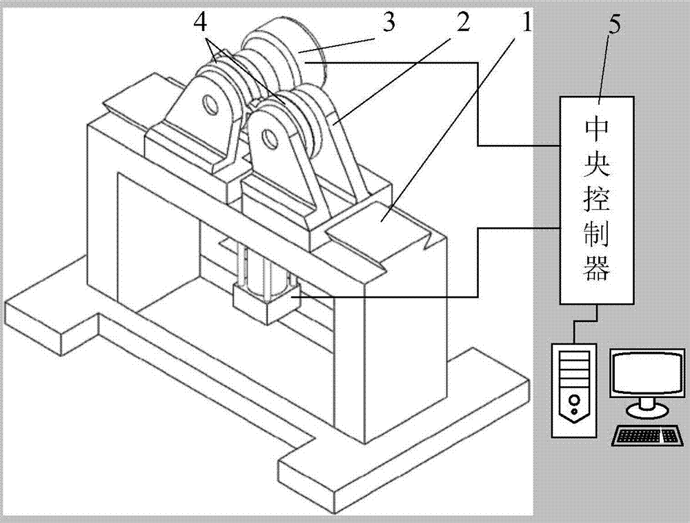
[0026] Such as figure 1 As shown, a fatigue test device for gear meshing includes a driving device 2 fixed on a base table 1, a simulated load device 3 and a test gear device 4, and the drive device 2 and the simulated load device 3 cooperate with the test gear device 4 respectively. The drive device 2 and the simulated load device 3 are respectively connected to the central controller 5, and the central controller 5 controls the drive device 2 by outputting a displacement-time curve signal, and controls the simulated load device 3 by outputting a load-time curve signal.

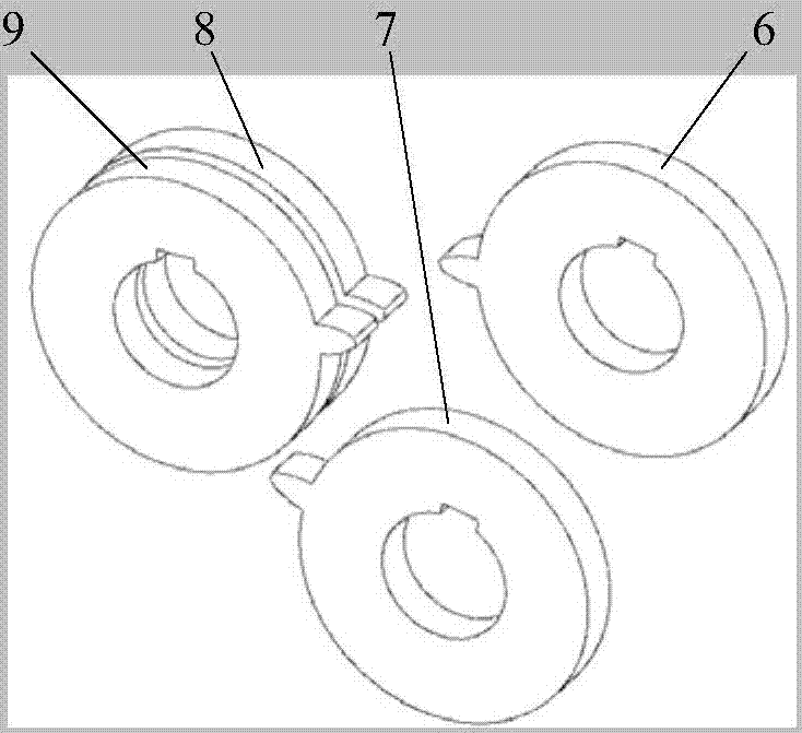
[0027] Such as figure 2 As shown, the test gear device 4 is composed of 4 single-tooth test gears, which are respectively the driving gear 7, the driven gear 9, the reset gear 6 and the reset gear 8, and the driving gear 7 is meshed with the 9 teeth of the driven gear. The ...


PUM


Abstract

The invention discloses a gear engagement fatigue testing device, and the device comprises a drive apparatus fixed on a foundation table, a simulation load apparatus, and a test gear apparatus. The drive apparatus and the simulation load apparatus respectively cooperate with the test gear apparatus, and are respectively connected with a central controller. The central controller controls the drive apparatus through outputting a displacement time curve signal, and controls the simulation load apparatus through outputting a load time curve signal. A brand-new loading process is employed to convert the meshing in a rotation process of a gear pair into the meshing in a reciprocating swinging process. The actual process of gear transmission is simulated, and a high-frequency big-period test can be carried out for a single tooth. The small-amplitude movement facilitates the building of the test apparatus, and the real-time performance and accuracy of stress and strain data collection in a gear failure process. The device is high in automation degree, is good in testing quality, is novel in testing loading method, and is suitable for the measurement of the related data in the gear transmission process.

Description

technical field [0001] The invention belongs to the technical field of gear fatigue life detection, in particular to a gear meshing fatigue test device and a test method thereof. Background technique [0002] Gearboxes are key components in wind turbines. In the reliability research process of wind power gear transmission systems, it is necessary to detect the stress state of the tooth surface and tooth root of the gear under specific working conditions to predict possible failure and fatigue life of the gear. . The current test methods related to gear strength include the gear bending fatigue strength test method recommended by the national standard (GB / T14230-93), which is divided into "bench running test" and "gear tooth pulsation loading test". The former is to conduct a load running test on the gear pair, and the latter is to use a special fixture on the pulsation fatigue testing machine to pulsate the teeth of the test gear. The disadvantage of the former is that the...

Claims


Application Information

Patent Timeline
IPC IPC(8): G01M13/02
CPCG01M13/021G01M13/027
Inventor 王辉张政向东刘天野田门吉雅
Owner TSINGHUA UNIV
Learn More