Distributed traveling wave range finding method

A traveling wave ranging and distributed technology, applied in the field of distributed traveling wave ranging, can solve the problem that the ranging accuracy cannot meet the ranging requirements, and achieve the effects of solving the problem of signal attenuation, convenient installation and simple structure

Active Publication Date: 2017-07-18
STATE GRID SHANDONG ELECTRIC POWER +1
View PDF9 Cites 22 Cited by
  • Summary
  • Abstract
  • Description
  • Claims
  • Application Information

AI Technical Summary

Problems solved by technology

[0010] Due to the large change in long-distance wave velocity, the ranging accuracy of traditional traveling wave ranging cannot meet the ranging requirements

Method used


Image

  • Distributed traveling wave range finding method
  • Distributed traveling wave range finding method
  • Distributed traveling wave range finding method

Examples


Embodiment Construction

[0033] The present invention will be further described below in conjunction with the accompanying drawings and embodiments.

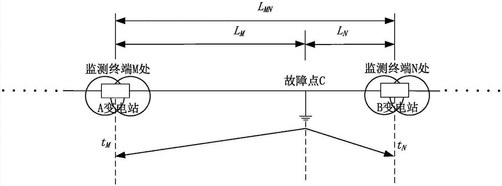
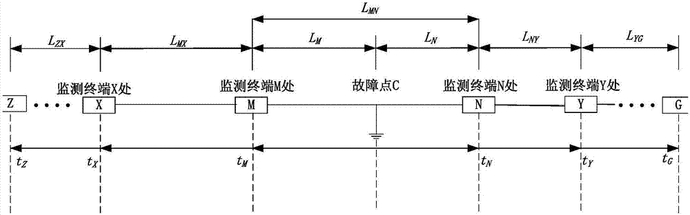
[0034] In order to solve the problem that the distance measurement accuracy cannot meet the distance measurement requirements when the traditional traveling wave ranging is used in the transmission line of the power system, this invention proposes a new type of distributed structure, which uses non-contact traveling wave acquisition and distributed traveling wave ranging algorithm The combined new method can accurately measure the fault distance in time, so that the power system can resume normal operation as soon as possible. The monitoring terminal is no longer limited to be installed in the substation, but adopts distributed installation, and the poles and towers along the transmission line are distributed according to a certain distance, and the traveling wave velocity is dynamically calculated, which is closer to the real value. The distance measur...


PUM


Abstract

The invention discloses a distributed traveling wave range finding method comprising the following steps: collecting traveling wave voltage and current data of multi-measuring point according to preset distances; timing and correcting the acquisition time; determining the initial traveling wave speed according to traveling wave time and measuring point distance measured on measuring points of two ends of the fault; determining the fault position according to the initial traveling wave speed, the distance of two adjacent measuring points, the fault propagation time to the measuring point, and two end range finding. The method distributes measuring points along power transmission line poles according to certain distances, and can dynamically measure the traveling wave speed approaching to the real value, thus solving the existing power transmission traveling wave monitoring problems, and ensuring the range finding precision under various complex conditions like high resistance grounding.

Description

technical field [0001] The invention relates to the field of distance measurement of power system transmission line faults, in particular to a distributed traveling wave distance measurement method. Background technique [0002] At present, when a fault occurs on a high-voltage transmission line, the method of traveling wave distance measurement is often used, and the traveling wave distance measurement device is installed in the substation of the transmission line. When a line fault occurs, the traveling wave will propagate along the transmission line to the front and rear sides respectively. The traveling wave ranging device at the station collects the fault traveling wave current, and then detects the propagation time of the fault transient current traveling wave between the fault point and the bus to locate the point of failure. [0003] For high-voltage power transmission systems with a transmission distance of hundreds to thousands of kilometers, due to the ultra-long...

Claims


Application Information

Patent Timeline
Patent Type & Authority Applications(China)
IPC IPC(8): G01R31/08
CPCG01R31/085
Inventor 姜忠福孟令军金运昌郭凯刘书娥
Owner STATE GRID SHANDONG ELECTRIC POWER
Why Eureka
Try Eureka