Surface mounted device (SMD) type inverted LED light source and manufacturing method thereof, and LED array

A technology of LED light source and manufacturing method, which is applied in semiconductor/solid-state device manufacturing, electrical components, electric solid-state devices, etc., can solve the problems of increased development cost, many models, and shiny, etc., to avoid the risk of gold wire breakage and reduce The effect of production cost and fast response

Inactive Publication Date: 2017-07-18
NINGBO SUNPU OPTO SEMICON
View PDF4 Cites 4 Cited by
  • Summary
  • Abstract
  • Description
  • Claims
  • Application Information

AI Technical Summary

Problems solved by technology

At the same time, the light-emitting area of ​​the existing COB light source is relatively fixed, and the heat dissipation substrate is large, so it is impossible to flexibly design the light spot, power, and central light intensity of different car lights, which leads to difficulties in combining light sources, such as figure 2 as shown, figure 2 It is a schematic diagram of different light source combinations in the prior art. When multiple first COB light sources are combined, there will be dark areas between the light-emitting surfaces, which cannot meet the requirements of the light spot of the car lights. Many, the combination is relatively rigid, and the development cost is greatly increased. Moreover, the existing internal circuit connection of the light source is bonded with gold wire or alloy wire. During production and use, the gold wire or alloy wire is easily broken under external force. As a result, bad conditions such as dead lights and flashing

Method used


Image

  • Surface mounted device (SMD) type inverted LED light source and manufacturing method thereof, and LED array
  • Surface mounted device (SMD) type inverted LED light source and manufacturing method thereof, and LED array
  • Surface mounted device (SMD) type inverted LED light source and manufacturing method thereof, and LED array

Examples


Embodiment Construction

[0033] The core idea of ​​the present invention is to provide a patch-type flip-chip LED light source and its manufacturing method and LED array, which can avoid the risk of gold wire breakage, and is small in size, can be combined flexibly, meets different design requirements, and has a fast response speed , can reduce production cost.

[0034] The following will clearly and completely describe the technical solutions in the embodiments of the present invention with reference to the accompanying drawings in the embodiments of the present invention. Obviously, the described embodiments are only some, not all, embodiments of the present invention. Based on the embodiments of the present invention, all other embodiments obtained by persons of ordinary skill in the art without making creative efforts belong to the protection scope of the present invention.

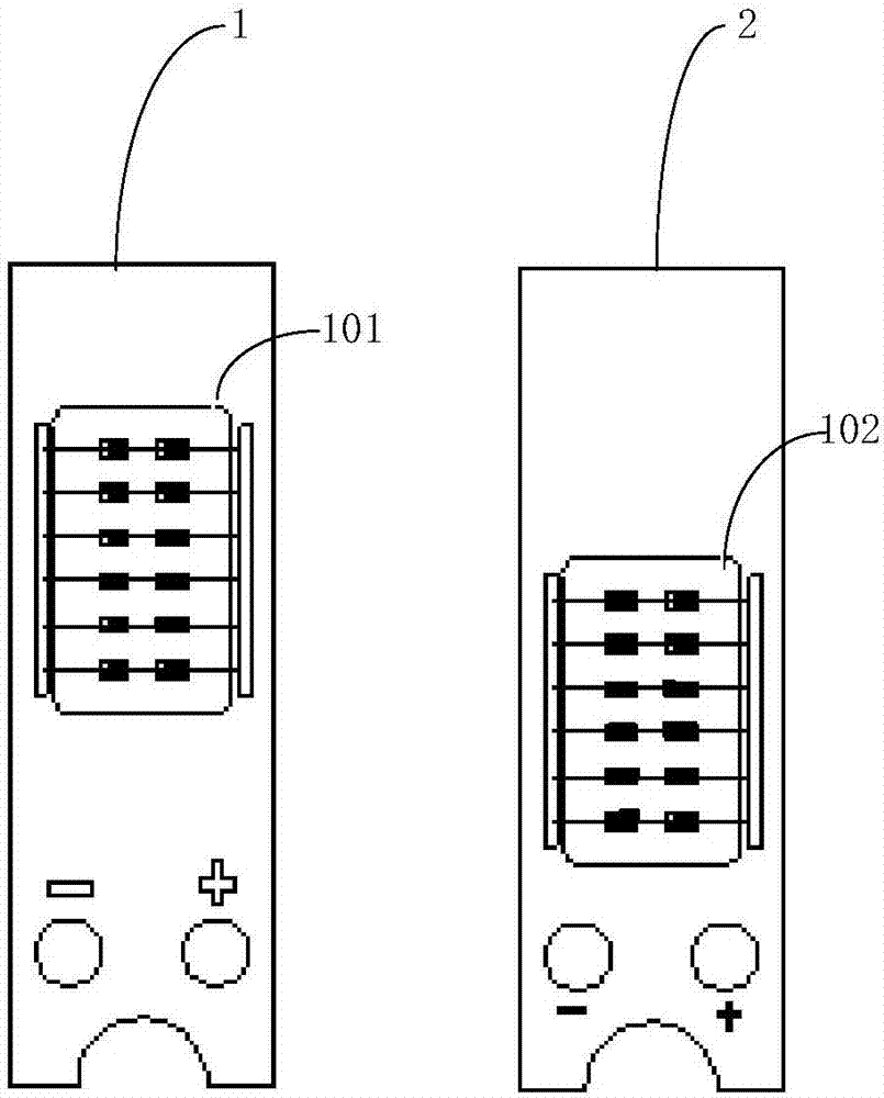
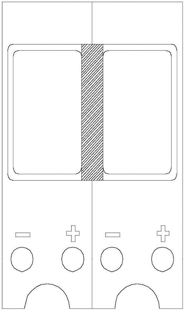
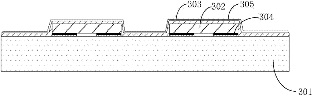
[0035] The first patch-type flip-chip LED light source provided by the embodiment of the present application is as follows:...


PUM


Abstract

The application discloses a chip-type flip-chip LED light source and its manufacturing method and LED array. The chip-type flip-chip LED light source includes a substrate with electrodes penetrating the upper surface and the lower surface. For a chip, the electrodes of the substrate are connected to the electrodes on the lower surface of the chip, and phosphor layers are provided on the upper surface of the substrate other than the chip bonding part and the upper surface of the chip. The LED array includes at least two patch-type flip-chip LED light sources, and the light-emitting parts of any adjacent two patch-type flip-chip LED light sources are closely adjacent to each other. The chip-type flip-chip LED light source and its manufacturing method and LED array can avoid the risk of broken gold wires, are small in size, can be combined flexibly, meet different design requirements, and have a fast response speed, which can reduce production costs.

Description

technical field [0001] The invention belongs to the technical field of lighting equipment manufacturing, and in particular relates to a patch-type flip-chip LED light source, a manufacturing method thereof, and an LED array. Background technique [0002] In the car light market, LED car lights have the advantages of energy saving, environmental protection, long life, high stability, and fast response speed. The LED car light market is booming and is gradually replacing traditional halogen lamps and xenon lamps. [0003] At present, most LED lights on the market use COB light sources. However, a COB light source corresponds to a fixed light-emitting surface (including the position and size of the light-emitting surface), and the same COB substrate cannot be used in the production of different light sources. . Such as figure 1 as shown, figure 1 It is a schematic diagram of a traditional COB light source, in which the substrate size of the first COB light source 1 and the s...

Claims


Application Information

Patent Timeline
Patent Type & Authority Applications(China)
IPC IPC(8): H01L33/62H01L25/075H01L21/60H01L21/78
CPCH01L2224/16225H01L33/62H01L21/78H01L24/83H01L24/94H01L25/0753H01L2224/83024H01L2224/97
Inventor 宓超张耀华蔡晓宁林胜张日光
Owner NINGBO SUNPU OPTO SEMICON
Why Eureka
Try Eureka