gas anesthesia system

A gas and anesthetic gas technology, applied in the direction of medicine equipment, other medical equipment, respirators, etc., can solve the problem of inability to accurately monitor the remaining amount of anesthetic in an anesthetic gas volatilizer, and achieve the effect of reducing losses

Active Publication Date: 2019-07-09
THE FIRST AFFILIATED HOSPITAL OF THIRD MILITARY MEDICAL UNIVERSITY OF PLA
View PDF11 Cites 1 Cited by
  • Summary
  • Abstract
  • Description
  • Claims
  • Application Information

AI Technical Summary

Problems solved by technology

[0007] The present invention intends to provide a gas anesthesia system to solve the problem that the existing gas anesthesia system cannot accurately monitor the remaining amount of anesthetic in the anesthesia gas volatilization tank

Method used


Image

  • gas anesthesia system
  • gas anesthesia system
  • gas anesthesia system

Examples


Embodiment Construction

[0039] The present invention will be described in further detail below by means of specific embodiments:

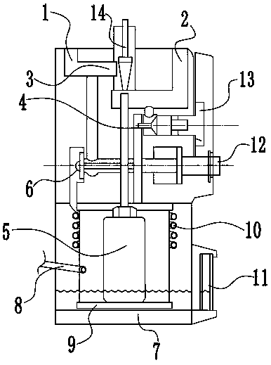
[0040] The reference signs in the drawings of the description include: air inlet 1, gas outlet 2, bypass passage 3, control hole 4, evaporation chamber 5, zero lock point 6, electronic scale 7, anesthetic input tube 8, temperature compensation device 9, Pressure compensation device 10, liquid level indicator 11, zero button 12, electric control knob 13, flow control cone 14, temperature sensor T1, first resistor R1, second resistor R2, third resistor R3, fourth resistor R4, first The fifth resistor R5, the sixth resistor R6, the seventh resistor R7, the eighth resistor R8, the ninth resistor R9, the tenth resistor R10, the first variable resistor RP1, the second variable resistor RP2, the first operational amplifier IC1, the The second operational amplifier IC2, the third operational amplifier IC3, and the triode Q1.

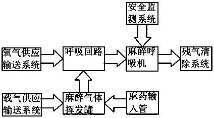
[0041] like figure 1 As shown, the gas anesthesia s...


PUM


Abstract

The patent application discloses a gas anesthesia system which comprises an anesthesia gas volatilization pot, wherein the anesthesia gas volatilization pot is connected to an anesthetic input pipe, and the end of the anesthetic input pipe stretching into the anesthesia gas volatilization pot is connected to a spraying nozzle; the bottom end of the anesthesia gas volatilization pot is in contact connection to an electronic balance; multiple heaters are disposed on the contact face between the electronic balance and the anesthesia gas volatilization pot; a temperature sensor and an in-pot pressure sensor are disposed in the anesthesia gas volatilization pot; a pressure sensor outside the pot and a flow rate sensor are disposed at a communicating position between the anesthesia gas volatilization pot and a breathing circuit; a micro controller and a display screen connected to the micro controller are disposed in a safety monitoring system; and the electronic balance, the heaters, the pressure sensor and the flow rate sensor are connected to a micro controller.

Description

technical field [0001] The invention relates to a medical device, in particular to a gas anesthesia system. Background technique [0002] In modern medical systems, an anesthesia machine used for patient anesthesia generally includes a gas supply delivery system for supplying oxygen and carrier gas, an anesthetic gas vaporizer connected to the gas supply delivery system through a switch valve, an anesthetic gas vaporizer and oxygen delivery system A breathing circuit connected to the system, an anesthesia ventilator connected to the breathing circuit through a switch valve, a safety monitoring system and a residual gas removal system connected to the anesthesia ventilator. [0003] Among them, the anesthesia gas vaporizer, also known as the evaporation chamber, is one of the important parts of the anesthesia machine. Its quality not only represents the overall quality level of the anesthesia machine, but also relates to the quality of the anesthesia effect, and it is directl...

Claims


Application Information

Patent Timeline
Patent Type & Authority Patents(China)
IPC IPC(8): A61M16/01A61M16/18
CPCA61M16/0003A61M16/01A61M16/18A61M2016/0027A61M2016/0033A61M2205/18A61M2205/33A61M2205/3368A61M2205/36
Inventor 吕锐杨贞易斌鲁开智
Owner THE FIRST AFFILIATED HOSPITAL OF THIRD MILITARY MEDICAL UNIVERSITY OF PLA
Why Eureka
Try Eureka