Intelligent grinding device for casting parts

A kind of parts and intelligent technology, applied in the field of grinding equipment, can solve the problems of not being able to realize the integral grinding of parts, affecting the processing efficiency and grinding time, and unable to guarantee the quality requirements of parts, so as to achieve a high degree of automation, improve grinding efficiency, facilitate maintenance and The effect of maintenance

Inactive Publication Date: 2017-07-21
KINHANYAN TECH DALIAN HLDG CO LTD
View PDF10 Cites 5 Cited by
  • Summary
  • Abstract
  • Description
  • Claims
  • Application Information

AI Technical Summary

Problems solved by technology

[0002] At present, casting parts such as cast iron and aluminum are more and more widely used. Since these casting parts need to remove risers, flashes, burrs, etc. in the actual processing process, the grinding of casting parts is a very important processing link. The traditional grinding process of casting parts mainly relies on artificial grinding wheels, which not only has low grinding efficiency, but also cannot guarantee the quality requirements of the parts; in order to improve the grinding efficiency, three-axis or four-axis machine tools are also used for grinding. However, the existing three-axis or four-axis Axis machine tools cannot realize the integral grinding of parts, especially for parts with irregular surfaces. The existing three-axis or four-axis machine tools cannot realize the grinding operation. In addition, the existing three-axis or four-axis machine tools only have one grinding wheel. The tool magazine cannot change tools according to different workpieces and actual processing needs, and requires multiple clamping, which directly affects processing efficiency and grinding time

Method used


Image

  • Intelligent grinding device for casting parts
  • Intelligent grinding device for casting parts

Examples


Embodiment Construction

[0015] Next, the present invention will be described in detail in conjunction with the accompanying drawings

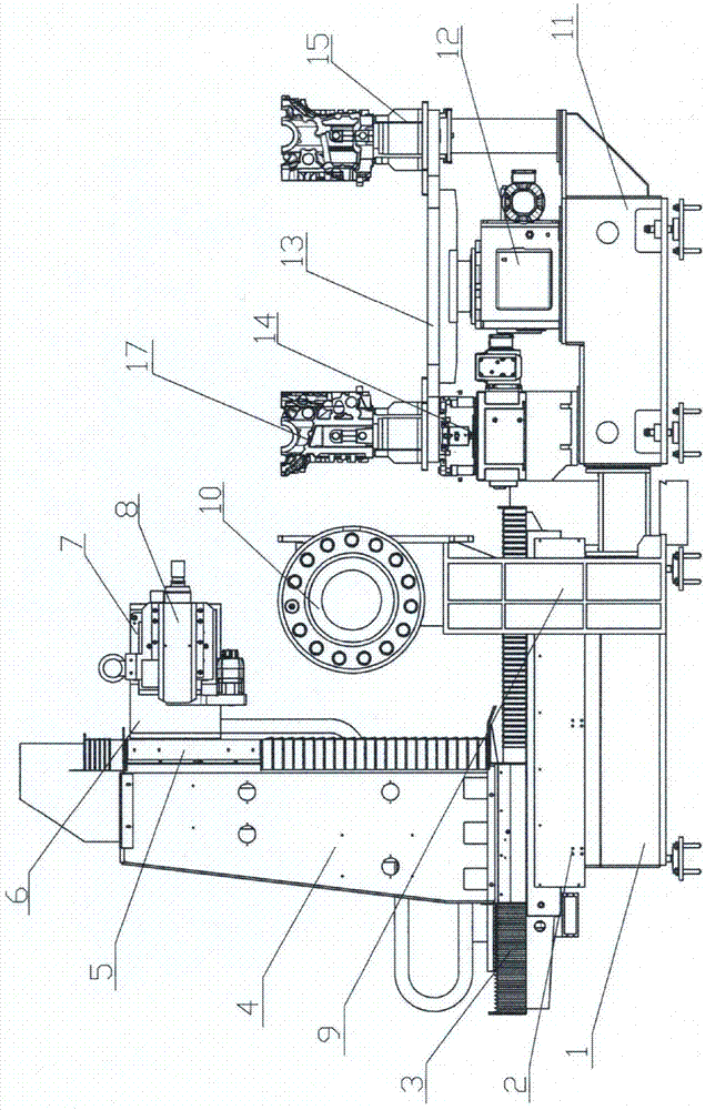
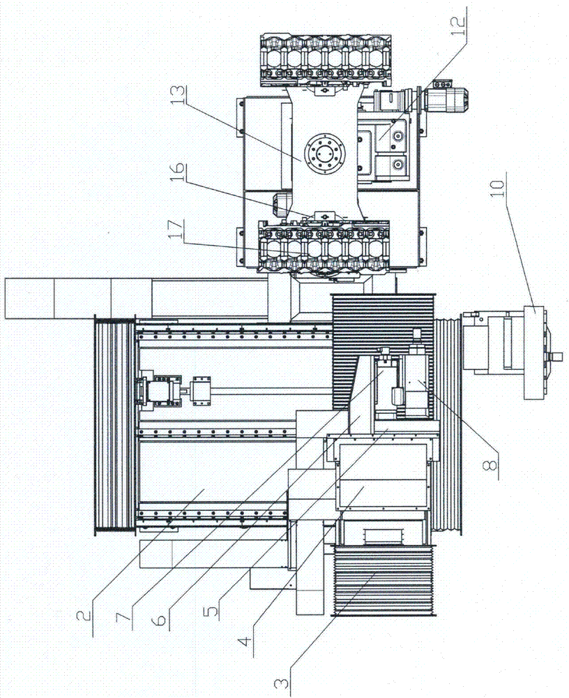
[0016] Such as figure 1 and figure 2 As shown, the first linear module 2 arranged along the Z direction is installed on the base 1, the second linear module 3 arranged along the X direction is installed on the slide table of the first linear module, and the slide of the second linear module A column 4 arranged along the Y direction is installed on the platform, and a third linear module 5 arranged along the Y direction is installed on one side of the column, and a connecting plate 6 is installed on the slide table of the third linear module, and an offset Set the swing head 7, and install the grinding main shaft 8 on the swing head body of the offset swing head, so as to realize the 0-90° swing of the grinding main shaft; a support 9 is arranged on one side of the Z direction of the base, and a tool magazine 10 is installed on the support; One side of the X directi...


PUM


Abstract

The invention discloses an intelligent grinding device for casting parts. A first linear module arranged in the Z direction is mounted on a base, a second linear module arranged in the X direction is mounted on a sliding table of the first linear module, a stand column arranged in the Y direction is arranged on a sliding table of the second linear module, a third liner module arranged in the Y direction is arranged on one side of the stand column, a connecting plate is mounted on a sliding table of the third linear module, an offset swing head is arranged on the connecting plate, a grinding spindle is arranged on a swing head body of the offset swing head, and a feeding and discharging assembly is arranged on the side in the X direction of the base. Compared with the prior art, the grinding device has the beneficial effects of being high in grinding efficiency, short in grinding time, capable of ensuring product machining precision and the like.

Description

technical field [0001] The invention relates to a mechanical processing equipment, in particular to a grinding equipment. Background technique [0002] At present, casting parts such as cast iron and aluminum are more and more widely used. Since these casting parts need to remove risers, flashes, burrs, etc. in the actual processing process, the grinding of casting parts is a very important processing link. The traditional grinding process of casting parts mainly relies on artificial grinding wheels, which not only has low grinding efficiency, but also cannot guarantee the quality requirements of the parts; in order to improve the grinding efficiency, three-axis or four-axis machine tools are also used for grinding. However, the existing three-axis or four-axis Axis machine tools cannot realize the integral grinding of parts, especially for parts with irregular surfaces. The existing three-axis or four-axis machine tools cannot realize grinding operations. In addition, the e...

Claims


Application Information

Patent Timeline
Patent Type & Authority Applications(China)
IPC IPC(8): B24B27/00B24B9/04B24B41/04B24B41/06
CPCB24B9/04B24B27/00B24B41/04B24B41/06
Inventor 姜作诚李承翰葛阳
Owner KINHANYAN TECH DALIAN HLDG CO LTD
Why Eureka
Try Eureka