

Earthquake disaster gas pipeline shutoff valve
A technology for gas pipelines and shut-off valves, applied in valve details, safety valves, balance valves, etc., can solve the problems of complex shut-off valves, inconvenient maintenance and maintenance, and high manufacturing costs
Active Publication Date: 2017-07-21
山东酷品智能科技有限公司
View PDF4 Cites 0 Cited by
- Summary
- Abstract
- Description
- Claims
- Application Information
AI Technical Summary
Problems solved by technology
[0002] At present, the closed valves for mechanical earthquake disaster gas pipelines that have been applied for or authorized are very complicated, with high manufacturing costs and inconvenient repair and maintenance.
Method used
View moreImage
Smart ImageViewing Examples

Examples
Embodiment Construction
[0009] SUMMARY OF THE INVENTION The specific embodiments of the present invention have been described in detail, and will not be repeated here.
Login to View More PUM
 Abstract
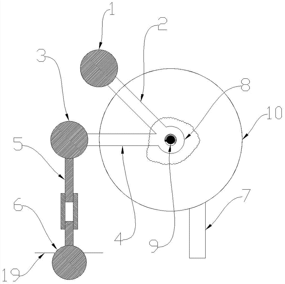
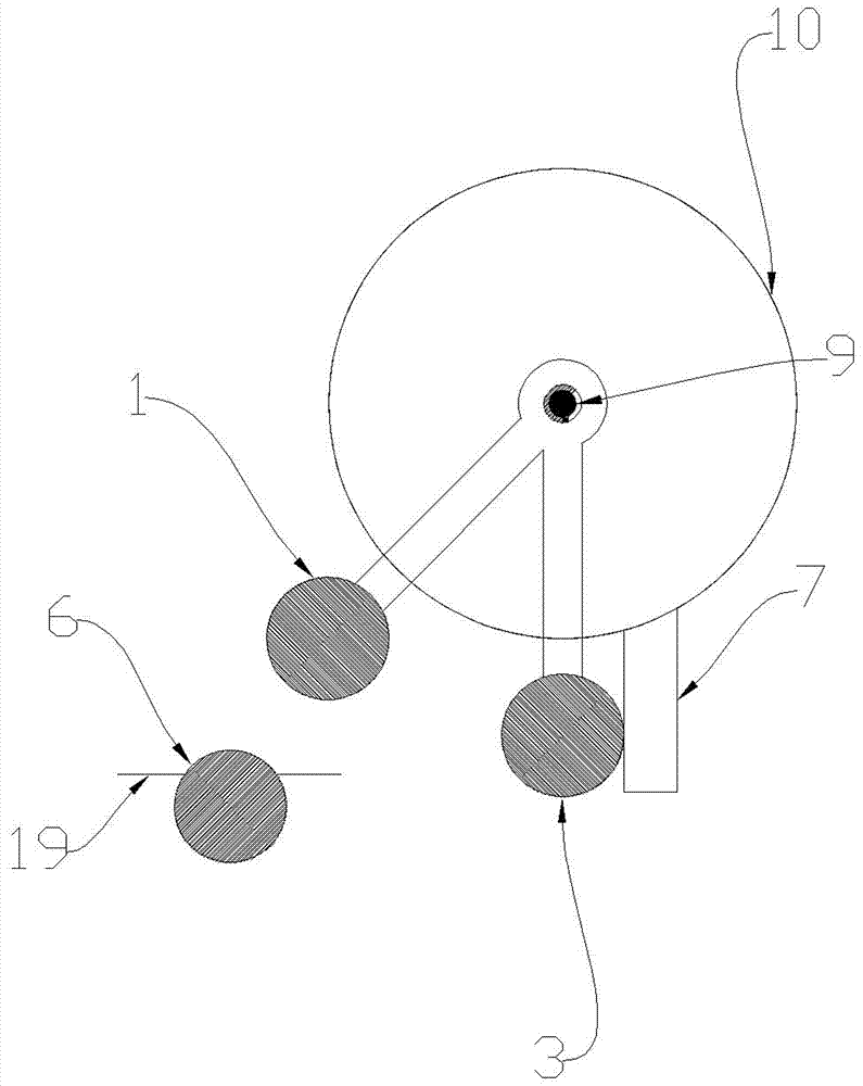
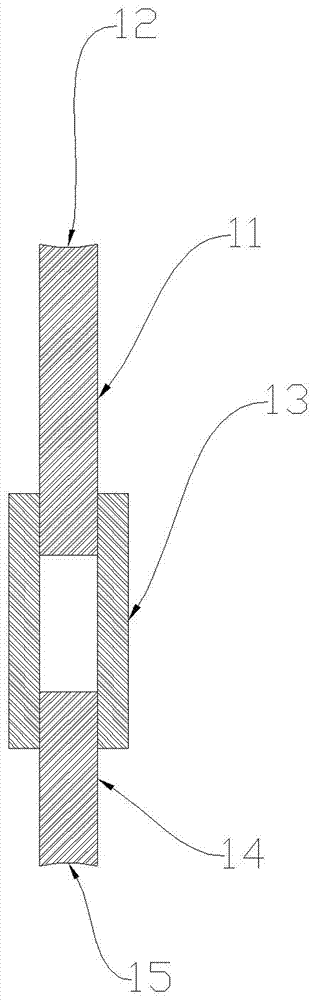
The invention provides an earthquake disaster gas pipeline shutoff valve. The earthquake disaster gas pipeline shutoff valve is mainly used for shutting off a gas pipeline valve body when an earthquake disaster occurs, is simple in structure, low in manufacturing cost and convenient to repair and maintain and is mainly composed of an upper gravity ball, a connecting rod A, a lower gravity ball, a connecting rod B, an ejector rod, a fixed ball, a baffle, a shaft sleeve, a butterfly valve rotary shaft and a butterfly valve body. The main working principle of the earthquake disaster gas pipeline shutoff valve is that the ejector rod is firstly mounted to enable a lower groove of the ejector rod to abut against the upper spherical surface of the fixed ball and meanwhile to enable an upper groove of the ejector rod to abut against the lower spherical surface of the fixed ball; when an earthquake occurs, the ejector rod can only fall towards the ground; the lower gravity ball counterclockwise rotates due the gravity effect and stops rotating after the spherical surfaces of the lower gravity ball collide the baffle; the butterfly valve body is just closed; the lower gravity ball can have certain clockwise resilience after colliding the baffle; and since a dead section exists, the resilience cannot drive the butterfly valve rotary shaft of the butterfly valve body to rotate, and closing of the butterfly valve body is not affected.
Description
Technical field [0001] The invention is mainly used for closing gas pipeline valves when earthquake disasters occur. Background technique [0002] At present, the mechanical shut-off valves for gas pipelines related to earthquake disasters that have been applied for or have been authorized are very complicated, high manufacturing costs, and inconvenient maintenance and maintenance. Summary of the invention [0003] The present invention overcomes the above-mentioned defects. It has simple structure, low manufacturing cost, convenient repair and maintenance. It is mainly composed of upper gravity ball (1), connecting rod A (2), lower gravity ball (3), and connecting rod B (4). , Mandrel (5), fixed ball (6), baffle (7), shaft sleeve (8), butterfly valve shaft (9), butterfly valve (10); the upper end of connecting rod A (2) and the gravity ball (1) ) Fixed, the lower end of connecting rod A (2) is fixed to the shaft sleeve (8), the left end of connecting rod B (4) is fixed to the lo...
Claims
Login to View More Application Information
Patent Timeline
 IPC IPC(8): F16K17/36F16K35/00
CPCF16K17/363F16K35/00
Inventor彭宝安
Owner山东酷品智能科技有限公司