Air conditioner water cold storage system

A water storage and air-conditioning technology, which is applied in air-conditioning systems, heating and ventilation control systems, heating and ventilation safety systems, etc. It can solve the problems of uncontrollable cold water flow of air-conditioning fan coil components, inability to modularize production, and difficulty in quality assurance. , to achieve the effect of simple structure, low cost and long service life

Inactive Publication Date: 2017-07-21
上海碳誉节能环保科技有限公司
View PDF7 Cites 6 Cited by
  • Summary
  • Abstract
  • Description
  • Claims
  • Application Information

AI Technical Summary

Problems solved by technology

[0003] Most of the cold storage tanks in the prior art are large in size, low in cold storage efficiency, large in floor area, inconvenient for transportation, and cannot be modularized, so they can only be produced on site, which not only affects the construction period, but also has certain limitations in on-site production. Uncertainty, quality is difficult to guarantee, leading to an increase in the risk factor, for public buildings or residential areas with small building areas, it is difficult to realize, and the disadvantages of long production cycle and large floor area have not yet appeared, and after the air-conditioning fan coil unit The cold water flow of the components cannot be controlled. When the flow and velocity are large, when the chilled water flows through the fan coil unit, there is not enough time to release all the cooling capacity it carries, and it returns to the water tank. Therefore, the chilled water pump does A lot of useless work, these are unnecessary energy consumption

Method used


Image

  • Air conditioner water cold storage system
  • Air conditioner water cold storage system

Examples


Embodiment Construction

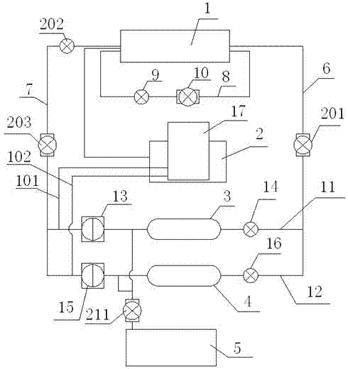
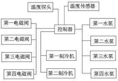
[0015] refer to figure 1 and figure 2 A kind of air-conditioning water cold storage system shown, comprises air-conditioning fan coil unit 1, pool 2, the first ice storage water tank 3, the second ice storage water tank 4, replenishing water tank 5 and controller, described air-conditioning fan coil unit 1 The water inlet end of the air conditioner is provided with a water inlet pipeline 6, the water outlet end of the air conditioner fan coil unit 1 is provided with a water outlet pipeline 7, and the air conditioner fan coil unit 1 is provided with a circulation pipeline 8, and the circulation pipeline 8 is provided with A third solenoid valve 9 and a first water pump 10 are provided, a first pipeline 11 and a second pipeline 12 are connected between the water inlet pipeline 6 and the water outlet pipeline 7, and the first ice storage tank 3 is arranged on On the first pipeline 11, the second ice storage tank 4 is arranged on the second pipeline 12, the first pipeline 11 on ...


PUM


Abstract

The invention discloses an air conditioner water cold storage system. The air conditioner water cold storage system comprises an air conditioner fan coil, a water pool, a first ice water storage tank, a second ice water storage tank, a water replenishing tank and a controller. The water inlet end of the air conditioner fan coil is provided with a water inlet pipeline. The water outlet end of the air conditioner fan coil is provided with a water outlet pipeline. The air conditioner fan coil is provided with a circulation pipeline. A first pipeline and a second pipeline are connected between the water inlet pipeline and the water outlet pipeline. The first ice water storage tank is arranged on the first pipeline. The second ice water storage tank is arranged on the second pipeline. A water return tank connected with the water outlet end of the air conditioner fan coil through a pipeline is arranged in the water pool. The water inlet pipeline is provided with a second water pump. The water outlet pipeline is provided with a third water pump and a fourth electromagnetic valve. A temperature sensor is arranged at the water outlet end of the air conditioner fan coil. A temperature probe is arranged in the air conditioner fan coil. The temperature sensor and the temperature probe are both connected with the controller. The water replenishing tank is connected with the first pipeline and the second pipeline through water pipes. The air conditioner energy consumption is lowered, and heat recycling of hot water obtained after heat exchange is achieved.

Description

technical field [0001] The invention relates to an air-conditioning water cold storage system. Background technique [0002] An obvious feature of my country's power supply in recent years is that there is a large difference between the "peak" load during the day and the "valley" load at night in summer, which reduces the load rate of the power grid; air conditioners are important power consumers and are also The main cause of the peak and valley load of the power grid, and the cold storage air conditioner is an effective way to solve this problem; the water cold storage air conditioner uses the peak and valley electricity price difference of the power grid, and uses chillers to store cold in the pool at night, and the pool is cooled during the day. The energy-saving air-conditioning mode of off-peak operation has the characteristics of small investment, reliable operation, good cooling effect and obvious economic benefits. In the case of large investment, complex commissionin...

Claims


Application Information

Patent Timeline
Patent Type & Authority Applications(China)
IPC IPC(8): F24F5/00F24F11/00F24F11/02
CPCF24F5/0017F24F11/89Y02E60/14
Inventor 陆天柱
Owner 上海碳誉节能环保科技有限公司
Why Eureka
Try Eureka