Solar following system and control method

A control method and solar energy technology, applied in the field of solar energy follower system and control, can solve problems such as low conversion rate, and achieve the effect of solving low conversion rate

Pending Publication Date: 2017-07-21
GUANGZHOU INST OF RAILWAY TECH
View PDF6 Cites 4 Cited by
  • Summary
  • Abstract
  • Description
  • Claims
  • Application Information

AI Technical Summary

Problems solved by technology

[0003] Based on this, the present invention overcomes the defect of low conversion rate in the prior art, and provides a solar tracking system and control method that improves the conversion rate of light energy, controls the collection device to always be perpendicular to sunlight, and makes full use of solar energy.

Method used


Image

  • Solar following system and control method
  • Solar following system and control method
  • Solar following system and control method

Examples


Embodiment approach 1

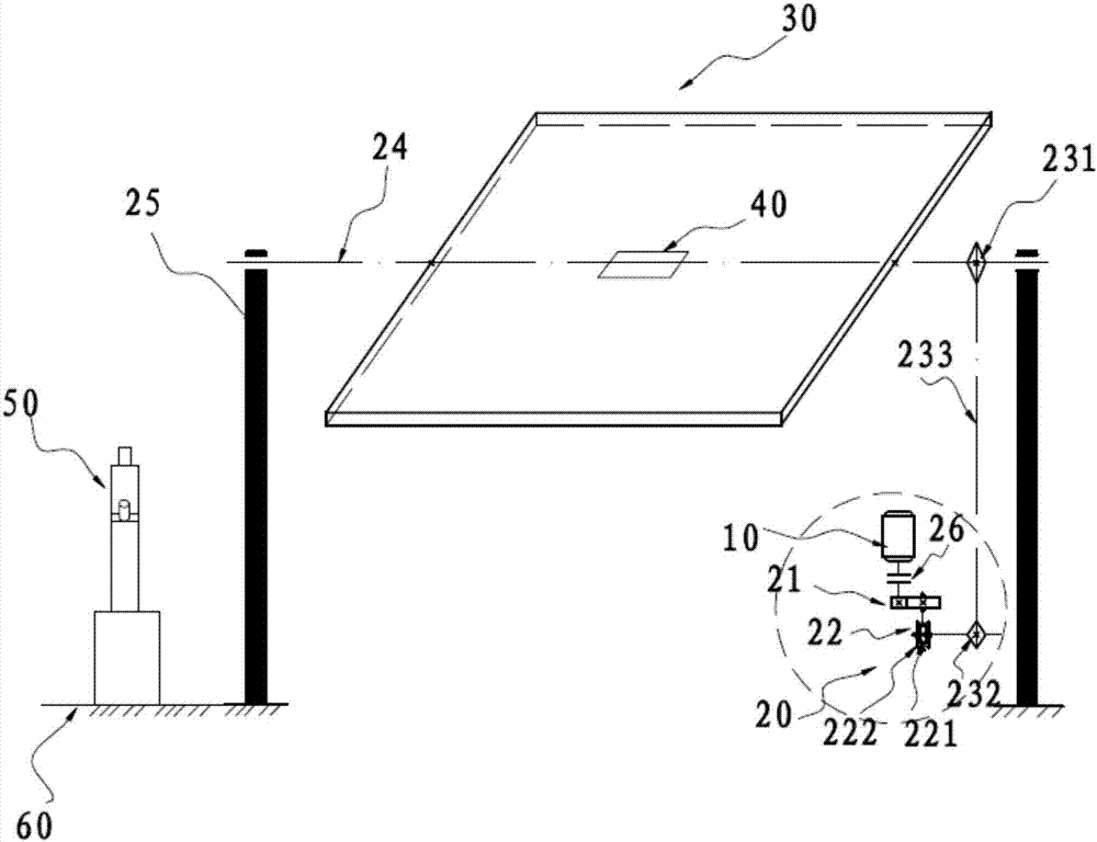
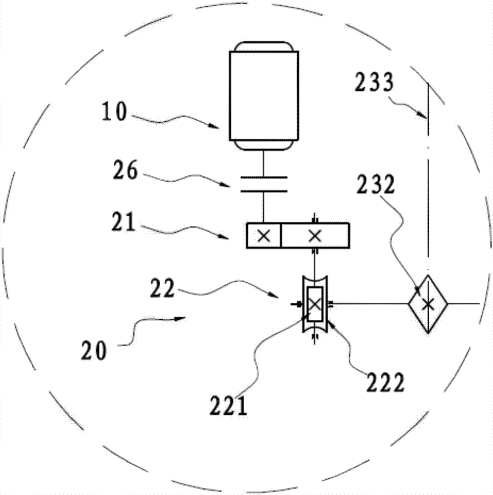
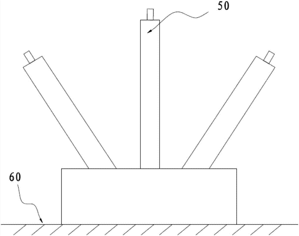
[0031] Such as figure 1A solar energy following system shown includes: a driving device 10, a transmission device 20, a collecting device 30, a first detecting device 40, a second detecting device 50 and a control device (not shown in the figure), and the driving device 10 The transmission device 20 is connected to the collection device 30, the control device controls the rotation of the drive device 10 so that the collection device 30 rotates, the first detection device 40 is arranged on the collection device 30, and the second detection device 50 is at least two The first detection device 40 and the second detection device 50 are both electrically connected to the control device. Turn on the solar energy following system. When the system initially runs, the control device drives the transmission device 20 by controlling the drive device 10, thereby controlling the collection device 30 connected to the transmission device 20 to automatically rotate. When the first detection d...

Embodiment approach 2

[0054] Such as Figure 4 As shown, the structure and principle of this embodiment are similar to Embodiment 1, the difference is that there are at least two first detection devices 40 in this embodiment, and the two first detection devices 40 are respectively arranged in the collection device 30 on both sides parallel to the first rotating shaft 24, when the light sources received by the two first detection devices 40 on both sides are balanced, it is the best position of the collection device 30, at this time the first detection device 40 sends The signal is sent to the control device, and the collecting device 30 is controlled to stop rotating.

Embodiment approach 3

[0056] The structure and principle of this embodiment are similar to Embodiment 1, the difference is that there are three first detection devices 40 in this embodiment, which are respectively arranged on the first detection device 40 and respectively arranged on the collection device 30 and the first detection device 40 respectively. The two sides parallel to the rotating shaft 24 and the middle position of the collection device 30, when the light intensity data received by the second detection device 50 located on both sides are greater than the light intensity data received by the second detection device 50 at the middle position, then control The forward and reverse motors rotate accordingly until the light source received by the second detection device 50 located on both sides and the second detection device 50 located in the middle is balanced, and the collecting device stops rotating.


PUM


Abstract

The invention discloses a solar following system. The solar following system comprises a driving device, a transmission device, a collection device, a first detection device, a second detection device and a control device. The invention also discloses a control method of the solar following system. When the system operates for the first time, the control device controls the collection device to automatically rotate. When the first detection device on the collection device receives an alignment light source, the collection device stops to rotate. When the illuminating angle of the sun is changed, the control device compares the angle position of the second detection device detecting the alignment light source with the angle device of the collection device, judges forward and backward rotation conditions of the driving device and drives the collection device to rotate through the driving device. When the first detection device on the collection device sends an instruction to the control device again, the collection device stops to rotate so as to allow the collection device to rotate along with the light source. Thus, a problem of low conversion efficiency of a solar system in the prior art is solved, and compared with the traditional fixed photovoltaic conversion rate of 10%-15%, the conversion rate is improved by around 22%.

Description

technical field [0001] The present invention relates to the energy field, and more specifically, to a solar energy following system and a control method. Background technique [0002] Solar panels can convert the light energy and heat energy emitted by the sun into electrical energy, thereby realizing solar power generation. Compared with traditional power generation methods, solar power generation itself does not use fuel, does not pollute the air, does not generate noise, and solar resources are inexhaustible. Inexhaustible; solar energy resources are available everywhere, and power can be supplied nearby; the power generation performance is stable and reliable, and the service life of the solar power generation system can reach more than 30 years. However, the traditional solar photovoltaic power generation in the market currently uses fixed photovoltaic panels, which can only convert 10% to 15% of the received sunlight energy into electrical energy, resulting in high pow...

Claims


Application Information

Patent Timeline
Patent Type & Authority Applications(China)
IPC IPC(8): G05D3/12H02S20/32
CPCH02S20/32G05D3/12Y02E10/50
Inventor 周玉海
Owner GUANGZHOU INST OF RAILWAY TECH
Why Eureka
Try Eureka