Solar moisture-proof power cabinet
A power cabinet and solar energy technology, which is applied in the field of solar moisture-proof power cabinets, can solve the problem that the power cabinet cannot prevent moisture and cool down.
- Summary
- Abstract
- Description
- Claims
- Application Information
AI Technical Summary
Problems solved by technology
Method used
Image
Examples
Embodiment 1
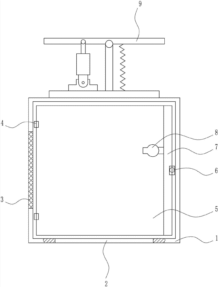
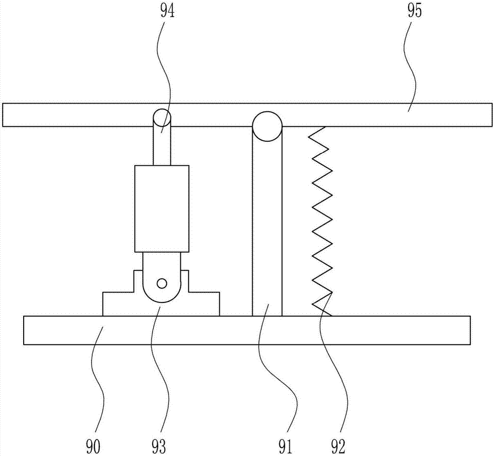
[0031] A solar moisture-proof power cabinet, such as Figure 1-5 As shown, it includes a box body 1, a first filter screen plate 3, a hinge 4, a box door 5, a door bolt 6, a lifting device 7, a fan 8 and a solar energy device 9, and the bottom of the box body 1 has a through hole 2, and the box body 1 The left wall of the body 1 is provided with a first filter screen plate 3, the left side of the front of the box body 1 is connected with a hinge 4, and the door 5 is connected to the hinge 4, the box door 5 is closely attached to the front of the box body 1, and the box body 1 The right side of the door 5 is provided with a door bolt 6, the door bolt 6 is connected with the box body 1, the inner right wall of the box body 1 is provided with a lifting device 7, the left side of the lifting device 7 is provided with a fan 8, and the top of the box body 1 is provided with a solar panel 95 .
Embodiment 2
[0033] A solar moisture-proof power cabinet, such as Figure 1-5 As shown, it includes a box body 1, a first filter screen plate 3, a hinge 4, a box door 5, a door bolt 6, a lifting device 7, a fan 8 and a solar energy device 9, and the bottom of the box body 1 has a through hole 2, and the box body 1 The left wall of the body 1 is provided with a first filter screen plate 3, the left side of the front of the box body 1 is connected with a hinge 4, and the door 5 is connected to the hinge 4, the box door 5 is closely attached to the front of the box body 1, and the box body 1 The right side of the door 5 is provided with a door bolt 6, the door bolt 6 is connected with the box body 1, the inner right wall of the box body 1 is provided with a lifting device 7, the left side of the lifting device 7 is provided with a fan 8, and the top of the box body 1 is provided with a solar panel 95 .
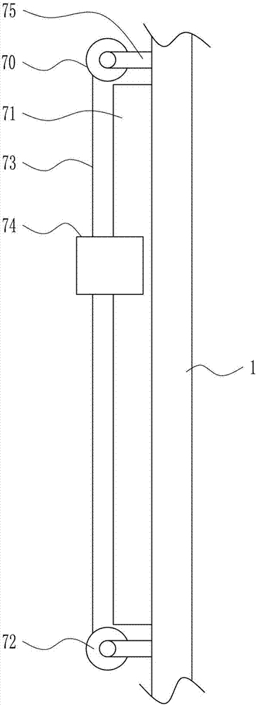
[0034] The lifting device 7 includes an upper electric reel 70, a slide rail 71, a lower...
Embodiment 3
[0036] A solar moisture-proof power cabinet, such as Figure 1-5As shown, it includes a box body 1, a first filter screen plate 3, a hinge 4, a box door 5, a door bolt 6, a lifting device 7, a fan 8 and a solar energy device 9, and the bottom of the box body 1 has a through hole 2, and the box body 1 The left wall of the body 1 is provided with a first filter screen plate 3, the left side of the front of the box body 1 is connected with a hinge 4, and the door 5 is connected to the hinge 4, the box door 5 is closely attached to the front of the box body 1, and the box body 1 The right side of the door 5 is provided with a door bolt 6, the door bolt 6 is connected with the box body 1, the inner right wall of the box body 1 is provided with a lifting device 7, the left side of the lifting device 7 is provided with a fan 8, and the top of the box body 1 is provided with a solar panel 95 .
[0037] The lifting device 7 includes an upper electric reel 70, a slide rail 71, a lower ...
PUM
 Abstract
Description
Claims
Application Information
 - R&D Engineer
- R&D Manager
- IP Professional
- Industry Leading Data Capabilities
- Powerful AI technology
- Patent DNA Extraction
Browse by: Latest US Patents, China's latest patents, Technical Efficacy Thesaurus, Application Domain, Technology Topic, Popular Technical Reports.
© 2024 PatSnap. All rights reserved.Legal|Privacy policy|Modern Slavery Act Transparency Statement|Sitemap|About US| Contact US: help@patsnap.com


