Buried type tool cabinet

A tool cabinet and underground technology, applied in the field of machinery and equipment, can solve the problems of physical exertion, inconvenient tool handling, etc., and achieve the effects of saving time, convenient access to tools and simple structure.

Inactive Publication Date: 2017-07-25
成都协恒科技有限公司
View PDF4 Cites 1 Cited by
  • Summary
  • Abstract
  • Description
  • Claims
  • Application Information

AI Technical Summary

Problems solved by technology

[0003] In order to solve the problems of inconvenient handling, physical exertion and production time of existing tools, the object of the present invention is to provide a buried tool cabinet

Method used


Image

  • Buried type tool cabinet
  • Buried type tool cabinet
  • Buried type tool cabinet

Examples


Embodiment 1

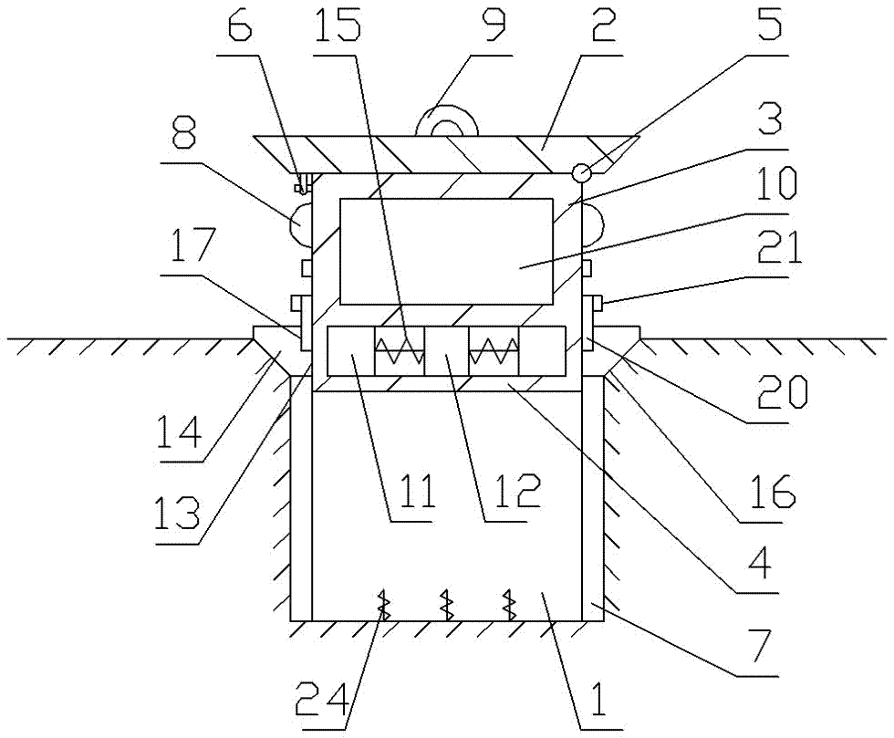
[0028] Such as Figure 1 to Figure 3 As shown, the bottom of the top cover 2 and the top of the side plate 3 are rotatably connected by a hinge 5, and on the side opposite to the hinge 5, the bottom of the top cover 2 and the top of the side plate 3 are connected by a latch 6; the inner wall of the pit 1 is vertically There are two slide rails 7, and each slide rail 7 is evenly distributed in the center of the pit 1; the outer wall of the side plate 3 is provided with pulleys 8, the number of pulleys 8 and the slide rails 7 are equal and the positions correspond to each other; the top of the top cover 2 is provided with handle9.

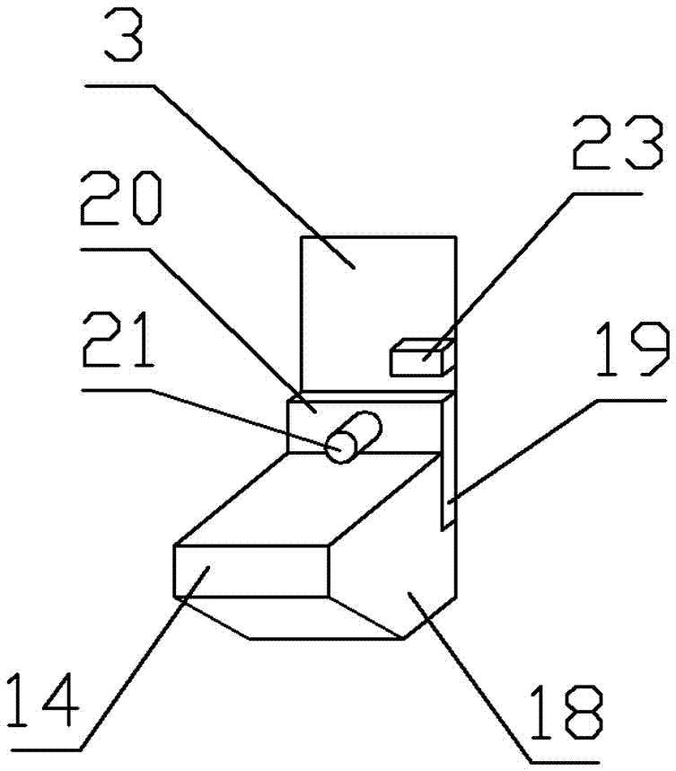
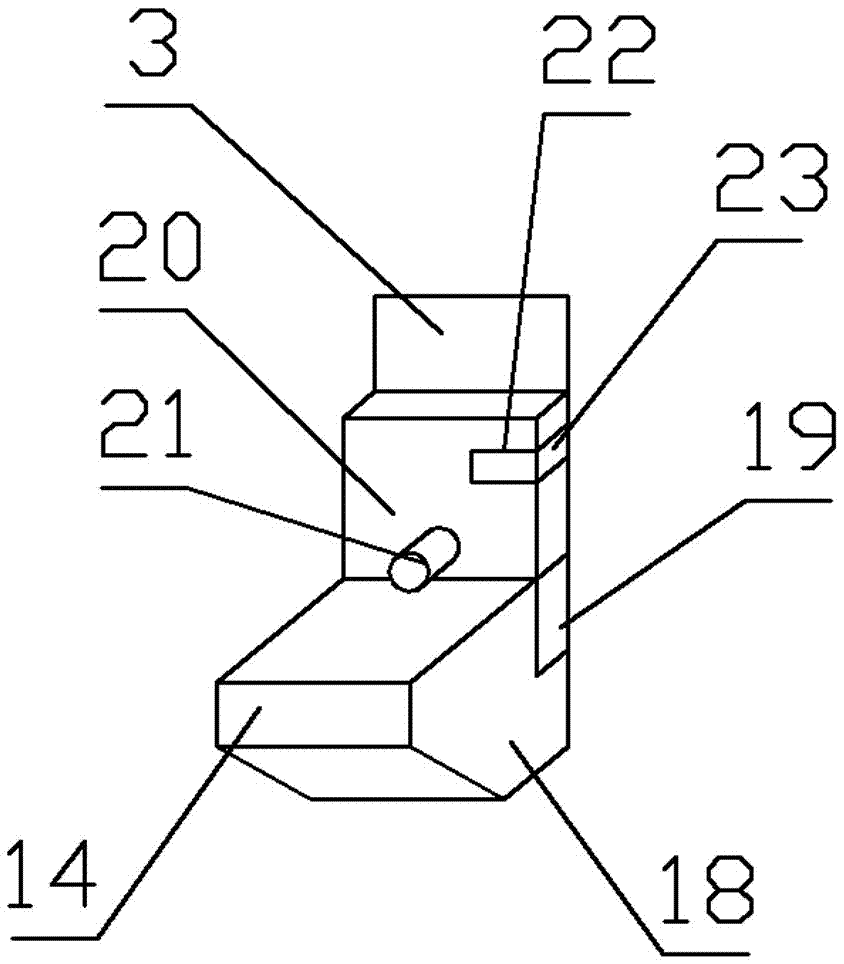
[0029] From top to bottom in the vertical direction, the interior of the cabinet is divided into a tool compartment 10 and a bottom compartment 11; a column 12 is fixed inside the bottom compartment 11, and the central axis of the column 12 corresponds to the center of the bottom plate 4; the side wall of the bottom compartment 11 is provided with 3...

Embodiment 2

[0035] Such as Figure 1 to Figure 3 As shown, the bottom of the top cover 2 and the top of the side plate 3 are rotatably connected by a hinge 5, and on the side opposite to the hinge 5, the bottom of the top cover 2 and the top of the side plate 3 are connected by a latch 6; the inner wall of the pit 1 is vertically There are two slide rails 7, and each slide rail 7 is evenly distributed in the center of the pit 1; the outer wall of the side plate 3 is provided with pulleys 8, the number of pulleys 8 and the slide rails 7 are equal and the positions correspond to each other; the top of the top cover 2 is provided with handle9.

[0036] From top to bottom in the vertical direction, the interior of the cabinet is divided into a tool compartment 10 and a bottom compartment 11; a column 12 is fixed inside the bottom compartment 11, and the central axis of the column 12 corresponds to the center of the bottom plate 4; the side wall of the bottom compartment 11 is provided with 3...

Embodiment 3

[0041] Such as Figure 1 to Figure 3 As shown, the bottom of the top cover 2 and the top of the side plate 3 are rotatably connected by a hinge 5, and on the side opposite to the hinge 5, the bottom of the top cover 2 and the top of the side plate 3 are connected by a latch 6; the inner wall of the pit 1 is vertically There are two slide rails 7, and each slide rail 7 is evenly distributed in the center of the pit 1; the outer wall of the side plate 3 is provided with pulleys 8, the number of pulleys 8 and the slide rails 7 are equal and the positions correspond to each other; the top of the top cover 2 is provided with handle9.

[0042] From top to bottom in the vertical direction, the interior of the cabinet is divided into a tool compartment 10 and a bottom compartment 11; a column 12 is fixed inside the bottom compartment 11, and the central axis of the column 12 corresponds to the center of the bottom plate 4; the side wall of the bottom compartment 11 is provided with 3...


PUM


Abstract

The invention discloses a buried type tool cabinet. The cabinet comprises a cabinet body arranged in the pit. The cabinet body comprises a top cover, a side plate and a bottom plate. The center of the bottom plate is corresponded to the center of the pit from up to down; the bottom of the top cover is rotatory connected to the bottom of the side plate through a hinge, one end opposite to the hinge and the bottom of the top cover are connected with the top of the side plate through a latch; at least two sliding rails are arranged in the inner wall of the pit along the vertical direction, and the sliding rails are evenly distributed according to center of the pit; a pulley is arranged at the outer wall of the side plate, the number of the pulley is equal to the number of the sliding rail and the position is in one-to-one correspondence; a lifting handle is arranged on the top of the top cover. The buried type tool cabinet has the advantages of eliminating the work of handling tools by manpower; saving time for enterprise production; reducing the labor force of workers; accessing the tools conveniently; being safe and reliable. The normal walking of the workers on the ground is not affected when the cabinet body is put into the pit.

Description

technical field [0001] The invention belongs to the technical field of mechanical equipment, and in particular relates to an underground tool cabinet. Background technique [0002] In the production workshop, workers need to use various hand tools when producing and processing various products. These hand tools often have the characteristics of small size and high quality. In daily production, workers often need to carry the tools from the tool storage place to the The production site, the transportation distance is long, the tools are of various types, large in quality, and in different shapes, which is very inconvenient to carry, which not only delays the production time, but also increases the physical labor of the workers. Therefore, it is very important to design a tool cabinet that is easy to use, improve the production efficiency of the enterprise, and reduce the physical labor of the workers. Contents of the invention [0003] In order to solve the problems of inc...

Claims


Application Information

Patent Timeline
Patent Type & Authority Applications(China)
IPC IPC(8): A47B81/00B25H3/00
CPCA47B81/00B25H3/00
Inventor 刘承范
Owner 成都协恒科技有限公司
Why Eureka
Try Eureka